Overall hoisted prefabricated underground continuous wall structure and prefabricating and construction method thereof

An underground diaphragm wall and hoisting technology, which is applied to underwater structures, infrastructure engineering, artificial islands, etc., can solve the problems of reducing the waterproof function of underground diaphragm walls, easy cracking and damage at joints, and small roots of mortise joints. Achieve the effects of shortening the construction period, facilitating subsequent processing, and improving strength

Inactive Publication Date: 2018-06-05
SHANGHAI APPLIED TECHNOLOGIES COLLEGE
13 Cites 2 Cited by

AI-Extracted Technical Summary

Problems solved by technology

However, the root of this kind of mortise joint is small, and the relative rotation between the walls is easy to occur and cannot withstand large lateral earth pressure. The joint is easy to crack and damage, resulting in leakage at the joint
In order to prevent the concrete of the prefabricated undergroun...

Method used

A kind of integral hoisting type prefabricated underground diaphragm wall provided by the present invention needs to finish prefabrication in factory, and making maintenance condition is man-made control, can guarantee the quality of concrete better, underground diaphragm wall is integral prefabrication, later stage need not pour concrete, During the construction process, the crane can be used for hoisting and assembling, which greatly shortens the construction period and improves the construction efficiency. The side of the wall adopts the pretensioning method to add prestressed steel bars 3, which effectively improves the wall strength of the diaphragm wall, can withstand large lateral earth pressure, and can avoid damage to the prefabricated underground diaphragm wall during transportation. In the prefabrication process, there are steel bars 6 protruding from the top of the diaphragm wall, which eliminates the need to chisel off a large amount of top concrete after the construction of the underground diaphragm wall in the traditional construction process, which can reduce resource consumption and facilitate subsequent processing. Help to improve construction efficiency. The joints of the continuous walls are designed with three groups of mortise joint structures, which are symmetrically distributed, which greatly improves the strength of the joints, and can effectively prevent sliding and misalignment between the continuous walls, making the connection more compact and firm. Water-swelling rubber water-stop strips 1 are provided on both sides of the wall at the butt joint of the prefabricated underground diaphragm wall. The water-swellable rubber water-stop strips 1 expand three times in volume when encountering water, and can The water-swellable rubber water-stop strip 1 is closely combined with the walls of the two adjacent continuous walls, and the two lines of defense can effectively prevent the entry of water and silt and prevent seepage.
[0031] As shown in Figure 1, it is a schematic structural view of a whole hoisting type prefabricated underground diaphragm wall provided by the present invention. It includes a prefabricated underground diaphragm wall body 2, the two ends of the prefabricated underground diaphragm wall body 2 are correspondingly provided with mortise joints 4, and the two sides of the wall body at the butt joint of the prefabricated underground diaphragm wall are respectively provided with water stop grooves 7. The water-swellable rubber water-stop strip 1 is provided in the water-stop groove 7 . The water-swellable rubber water-stop strip 1 can swell three times in volume after being exposed to water, and can fully fill the gap of the water-stop joint 5, and has an excellent waterproof effect. The water-swellable rubber water-stop strip 1 is placed in the water-stop groove 7. When the external water seeps into the continuous wall, it must first pass through the water-stop groove 7, and then pass through the water-expandable rubber water-stop strip 1. The structure of the water-stop groove 7 When the first layer of waterproof effect...

Abstract

The invention discloses an overall hoisted prefabricated underground continuous wall structure and a prefabricating and construction method thereof. The overall hoisted prefabricated underground continuous wall structure comprises a prefabricated underground continuous wall body, joggling joints are correspondingly arranged at both ends of the prefabricated underground continuous wall body, and sealing grooves are formed respectively in the two sides of the wall body at the butt joint portion of a prefabricated underground continuous wall and are internally provided with water-swelling rubbersealing strips. The butt joint portion of the prefabricated underground continuous wall body is provided with a waterproof joggling structure, the strength is high, slide and dislocation occurring between the wall bodies can be effectively prevented, the waterproof function is achieved, and concrete cracking can be prevented; prestress steel bars are arranged at the two sides of the wall body, thestrength of the wall body can be improved, and the wall body is prevented from being damaged in the transportation process; the steel bars are reserved at the top of the wall body and facilitate subsequent machining; besides, the prefabricated underground continuous wall is prefabricated integrally, concrete pouring is not required later, and a crane is adopted for hoisting and assembly in the construction process, which helps to shorten the construction period.

Application Domain

Artificial islandsProtective foundation +2

Technology Topic

DislocationButt joint +4

Image

  • Overall hoisted prefabricated underground continuous wall structure and prefabricating and construction method thereof
  • Overall hoisted prefabricated underground continuous wall structure and prefabricating and construction method thereof
  • Overall hoisted prefabricated underground continuous wall structure and prefabricating and construction method thereof

Examples

  • Experimental program(1)

Example Embodiment

[0030] The present invention will be further described below in conjunction with specific embodiments and accompanying drawings, so as to help understand the content of the present invention.
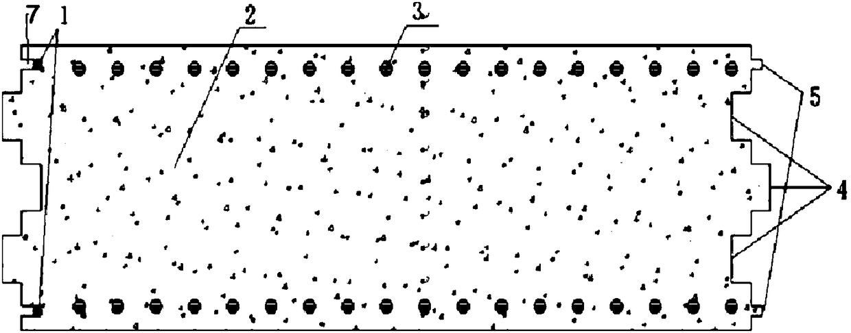
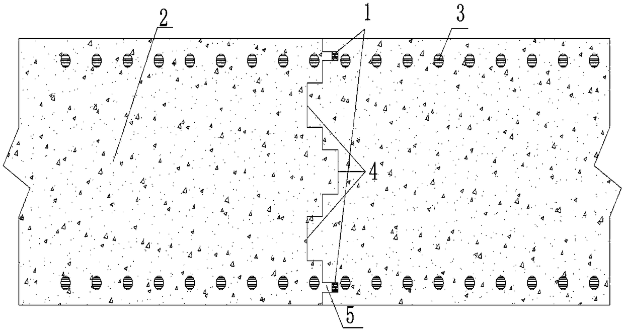
[0031] like figure 1 As shown, it is a structural schematic diagram of an integral hoisting prefabricated underground diaphragm wall body provided by the present invention. It includes a prefabricated underground diaphragm wall body 2, the two ends of the prefabricated underground diaphragm wall body 2 are correspondingly provided with mortise joints 4, and the two sides of the wall body at the butt joint of the prefabricated underground diaphragm wall are respectively provided with water stop grooves 7. The water-swellable rubber water-stop strip 1 is provided in the water-stop groove 7 . The water-swellable rubber water-stop strip 1 can swell three times in volume after being exposed to water, and can fully fill the gap of the water-stop joint 5, and has an excellent waterproof effect. The water-swellable rubber water-stop strip 1 is placed in the water-stop groove 7. When the external water seeps into the continuous wall, it must first pass through the water-stop groove 7, and then pass through the water-expandable rubber water-stop strip 1. The structure of the water-stop groove 7 When the first layer of waterproof effect is reached, it forms a double protection with the water-swellable rubber waterstop strip 1. The two lines of defense can effectively prevent the entry of water and sediment, and prevent seepage. The mortise joints 4 are divided into three groups and distributed symmetrically, which greatly improves the strength of the joints and can effectively prevent sliding and misalignment between the continuous walls, making the connection more compact and firm. Preferably, the mortise joint 4 is rectangular. Both sides of the prefabricated underground diaphragm wall are provided with prestressed steel bars 3 . The strength of the prefabricated underground diaphragm wall is effectively increased, and the prefabricated underground diaphragm wall can withstand large lateral earth pressure, and can avoid damage to the prefabricated underground diaphragm wall during transportation. A steel bar 6 is reserved above the prefabricated underground diaphragm wall body 2 (such as image 3 shown). It can eliminate the need to chisel off a large amount of top concrete after the construction of the underground diaphragm wall in the traditional construction process, reduce resource consumption, facilitate subsequent processing, and help improve construction efficiency. Preferably, the length of the steel bars 6 reserved above the prefabricated underground continuous wall body 2 is 1 m.
[0032] The prefabrication method of the overall hoisting prefabricated underground continuous wall structure includes the following steps: firstly, the reinforcement is configured according to the calculation requirements and the reinforcement cage is rolled. Then, the pre-tensioning method is used to prefabricate the wall part of the underground diaphragm wall. According to the design specifications, the reinforcement cage is first placed in the factory, and the prestressed tendons on both sides of the reinforcement cage are locked and stretched with prestressed anchors. After the tensioning is completed, concrete is poured. During the prefabrication process of the continuous wall, the steel bar 6 at the top of the wall needs to be reserved for 1m to protrude out of the concrete. The underground diaphragm wall needs to be cured by steam in the later stage to ensure the quality of the concrete.
[0033]The integral hoisting prefabricated underground diaphragm wall provided by the present invention needs to be prefabricated in the factory, and the production and maintenance conditions are controlled manually, which can better ensure the quality of the concrete. Use a crane to lift and assemble, which greatly shortens the construction period and improves construction efficiency. The side of the wall adopts the pretensioning method to add prestressed steel bars 3, which effectively improves the wall strength of the diaphragm wall, can withstand large lateral earth pressure, and can avoid damage to the prefabricated underground diaphragm wall during transportation. In the prefabrication process, there are steel bars 6 protruding from the top of the diaphragm wall, which eliminates the need to chisel off a large amount of top concrete after the construction of the underground diaphragm wall in the traditional construction process, which can reduce resource consumption and facilitate subsequent processing. Help to improve construction efficiency. The joints of the continuous walls are designed with three groups of mortise joint structures, which are symmetrically distributed, which greatly improves the strength of the joints, and can effectively prevent sliding and misalignment between the continuous walls, making the connection more compact and firm. Water-swelling rubber water-stop strips 1 are provided on both sides of the wall at the butt joint of the prefabricated underground diaphragm wall. The water-swellable rubber water-stop strips 1 expand three times in volume when encountering water, and can The water-swellable rubber water-stop strip 1 is closely combined with the walls of the two adjacent continuous walls, and the two lines of defense can effectively prevent the entry of water and silt and prevent seepage.
[0034] The construction method of the overall hoisting prefabricated underground diaphragm wall structure comprises the following steps: before the excavation of the groove section, a guide wall is constructed along the longitudinal axis of the diaphragm wall, and cast-in-situ concrete or reinforced concrete is used for pouring. The depth of the guide wall is 1.2-1.5m, and its top surface is 10-15cm higher than the ground to prevent surface water from flowing into the guide ditch. The width of the guide wall is 10cm wider than the wall thickness of the prefabricated underground continuous wall. The sinker is used to excavate the groove section. After the groove section is excavated, the single prefabricated underground diaphragm wall is hoisted by a large crane and put into the groove. When the next diaphragm wall is hoisted, the crane strictly controls the continuous The position of the wall, so that the mortise joint 4 and the water stop joint 5 of two adjacent walls can be neatly and closely connected (such as figure 2 shown). After the two continuous walls are stabilized, other continuous walls are placed in sequence according to this method. The mortise joint design of the water stop groove 7 can more effectively prevent the entry of external water. Both sides of the wall at the joint of the continuous wall are provided with a water-stop groove 7, and the water-swellable rubber water-stop strip 1 is arranged in the water-stop groove 7, which plays a double protective role and can effectively prevent the occurrence of seepage. Three groups of symmetrical mortise joints 4 can effectively prevent relative sliding and misalignment between the continuous walls, making the connection more compact and firm.
[0035] In this paper, specific examples are used to illustrate the inventive concept in detail, and the descriptions of the above embodiments are only used to help understand the core idea of ​​the present invention. It should be pointed out that for those skilled in the art, any obvious modification, equivalent replacement or other improvement should be included in the protection scope of the present invention without departing from the inventive concept.

PUM

PropertyMeasurementUnit
Length1.0m

Description & Claims & Application Information

We can also present the details of the Description, Claims and Application information to help users get a comprehensive understanding of the technical details of the patent, such as background art, summary of invention, brief description of drawings, description of embodiments, and other original content. On the other hand, users can also determine the specific scope of protection of the technology through the list of claims; as well as understand the changes in the life cycle of the technology with the presentation of the patent timeline. Login to view more.

Similar technology patents

Air ventilator for helmet

InactiveUS20070192942A1improve assemblability and stabilityquality assurance
Owner:J E TECH CO LTD

Preparation method of AdBlue

Owner:INNOVATIVE COAL CHEMICAL DESIGN INSTITUTE (SHANGHAI) CO LTD

Image-text superposing method and device

InactiveCN107205165AHigh system integrationQuality assurance
Owner:成都德芯数字科技股份有限公司

Blinder type dizziness detector

Owner:LANZHOU UNIVERSITY

Classification and recommendation of technical efficacy words

  • Quality assurance
  • Shorten the construction period

Fruit and vegetable logistics fresh-keeping transportation control system

InactiveCN102495595AQuality assuranceImprove automation and work efficiency
Owner:TIANJIN UNIVERSITY OF SCIENCE AND TECHNOLOGY

Automatic butt welding equipment for metal sheet

InactiveCN101780589AGuaranteed accuracy and efficiencyQuality assurance
Owner:上海新亚焊割成套设备有限公司

Box type high-voltage heater

ActiveCN103557514AShorten the construction periodAvoid the risk of temperature difference deformation
Owner:孔泽学 +1

Special soft foundation consolidation method

ActiveCN101324063AShorten the construction periodEasy and safe to operate
Owner:SHANGHAI HARBOUR SOFT SOIL TREATMENT ENG CO LTD

Intelligent LED lamp controller and control method

Owner:杭州罗莱迪思科技股份有限公司

Construction method of lattice light-gauge steel house

InactiveCN103104094Ashort setting timeShorten the construction period
Owner:成都绿建科技有限公司
Why Eureka
Try Eureka