Hot-press sealing paper bag producing machine

A bag making machine and paper bag technology, applied in bag making operations, container manufacturing machinery, paper making, etc., can solve the problem of slippage of the cutting knife and the feeding paper bag, and achieve the goal of ensuring cutting quality, reducing vibration and reducing noise. Effect

Pending Publication Date: 2018-06-08
陈国荣
View PDF1 Cites 0 Cited by
  • Summary
  • Abstract
  • Description
  • Claims
  • Application Information

AI Technical Summary

Problems solved by technology

[0005] The object of the present invention is to provide a heat-press sealing paper bag making machine in order to solve the problem of slippage between the cutting knife and the fed paper bag

Method used


Image

  • Hot-press sealing paper bag producing machine
  • Hot-press sealing paper bag producing machine
  • Hot-press sealing paper bag producing machine

Examples


Embodiment 1

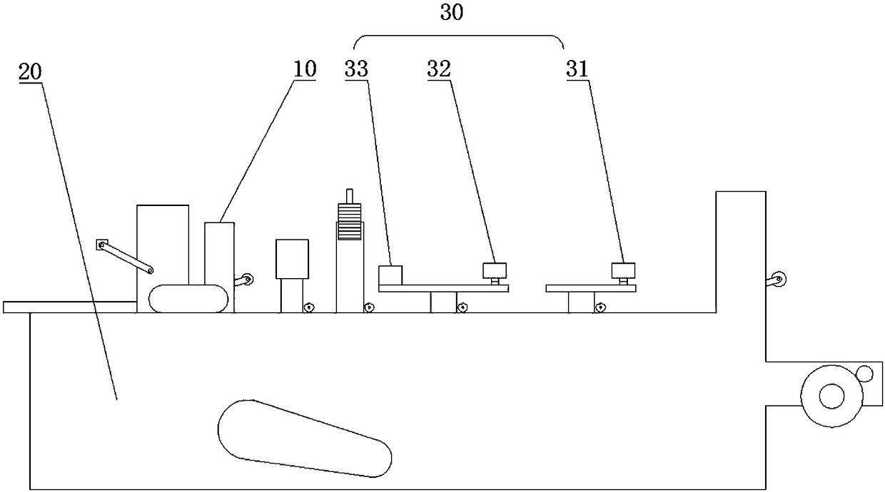
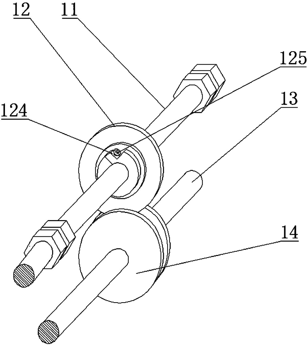
[0047] A hot-press sealing paper bag making machine, comprising a frame 20, a cutting device 10 is arranged on the frame 20, the cutting device includes an upper cutter bar 11, a circular cutter 12 is arranged on the upper cutter bar, and a main shaft is also included 13. The main shaft 13 is located below the upper knife bar 11. The main shaft 13 is provided with a lower knife groove 14. The lower knife groove 14 is set correspondingly to the circular cutter 12. The blade 121 of the circular cutter 12 is connected to the notch of the lower knife groove 14. One side wall or two side walls are in contact.

[0048] In the present embodiment, the circular cutter 12 is arranged on the upper knife bar 11, and the main shaft 13 is arranged below the upper knife bar 11, and the lower knife groove 14 corresponding to the circular cutter 12 is arranged on the said main shaft 13, and the circular cutter 12 The blade 121 is in contact with one side wall or both side walls of the notch of...

Embodiment 2

[0050] On the basis of Embodiment 1, the upper cutter bar 11 is fixed on the frame 20, and the circular cutter 12 is sleeved on the upper cutter bar 11 through a bearing.

[0051] In the present embodiment, the upper cutter bar 11 is fixed on the frame 20 of the bag making machine, and the circular cutter 12 is sleeved on the upper cutter bar 11 by a bearing. Therefore, in the course of work, only the circular cutter 12 rotates under the frictional force of the lower knife groove 14, while the upper knife bar 11 is fixed. By changing the traditional way that the upper knife rod is set on the frame through bearings, it avoids the need to set the gear on the upper knife rod to mesh with the chassis in the traditional way, or the situation that the upper knife rod rotates around its own axis, and reduces the burden on the upper knife. The vibration between the rod and the frame greatly reduces the noise during production.

Embodiment 3

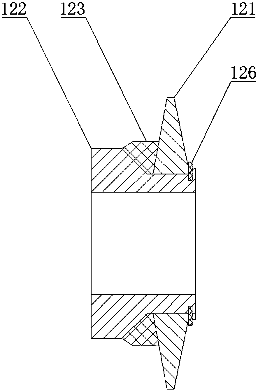
[0053] On the basis of Embodiment 2, the circular cutter 12 includes a cutter seat 122, and a blade groove is arranged on the cutter seat 122, and the blade 121 is sleeved on the blade groove, and between the left end surface of the blade 121 and the side wall of the blade groove An elastic element 123 is provided, and the left end surface of the blade 121 and the side wall of the blade slot are in contact with the elastic element 123 .

[0054] In this embodiment, the circular cutter 12 includes a cutter seat 122, a blade groove is arranged on the cutter seat 122, the blade 121 is sleeved on the blade groove, and elastic The element 123 , and the left end surface of the blade 121 , and the side wall of the blade slot are all in contact with the elastic element 123 . The blade 121 is rotated by the lower slit 14 through frictional force. During the production process, the blade 121 will follow the feeding of the paper bag to keep a slight floating left and right, so as to avoi...


PUM


Abstract

The invention discloses a hot-press sealing paper bag producing machine, and belongs to the field of paper bag making machines. In order to solve the problem of slippage between a cutting knife and fed paper bags, the machine comprises a frame, the frame is provided with a cutting device, the cutting device comprises an upper cutter bar, the upper cutter bar is provided with a circular cutter, andfurther comprises a main shaft, the main shaft is located below the upper cutter bar, a lower cutter groove is formed in the main shaft, the lower cutter groove is disposed corresponding to the circular cutter, and the blade of the circular cutter is in contact with one side wall or both side walls of the notch of the lower cutter groove. The machine is used for producing paper bag products suchas envelope bags, test paper bags, medicine bags and the like.

Description

technical field [0001] The invention belongs to the field of paper bag making machines, and in particular relates to a paper bag making machine. Background technique [0002] The existing paper bag making machine includes devices such as feeding, guide folding, hot pressing, cutting, and unloading. The slitting device in the cutting device belongs to the fixed knife, which works at a fixed position. For other reasons, the edge of the blade will lose its sharpness, burrs will appear on the section of the slitting product, and even the section will be obviously irregular, and the product will be scrapped. Cause every working about 36h needs to be replaced, has reduced labor efficiency. [0003] The Chinese utility model "A self-rotating cutting tool for a lithium battery diaphragm slitting machine" (authorized announcement number CN203331082U) discloses a self-rotating cutting tool for a lithium battery diaphragm slitting machine, including a cylindrical knife rod, which is s...

Claims


Application Information

Patent Timeline
Patent Type & Authority Applications(China)
IPC IPC(8): B31B70/20B31B70/04B31B70/74B31B160/10
Inventor 陈国荣陈证廷
Owner 陈国荣
Why Eureka
Try Eureka