Walking wheel structure for narrow-width micro-cultivator

A technology of micro-tiller and walking wheel, which is applied in the directions of wheels, rims, transportation and packaging, can solve the problems of limiting the utilization rate of micro-tiller on sloping land, complex processing technology of walking wheels, and poor gripping effect of walking wheels, etc. To achieve the effect of reducing adverse effects, unaffected stability, and strengthening structural strength

Inactive Publication Date: 2018-06-08
何德珍
View PDF4 Cites 0 Cited by
  • Summary
  • Abstract
  • Description
  • Claims
  • Application Information

AI Technical Summary

Problems solved by technology

[0003] At present, the walking wheels of micro tillage machines generally use wide rubber wheels, which have a large contact area with the ground and are easy to compact the ground, which is not conducive to the root growth of crops.
At the same time, the walking wheels of the existing micro tillage machine do not have a good grip on the ground, and it is easy to idling and run away when the force is applied during the operation of the cultivated land, which limits the utilization rate of the micro tillage machine on sloping land
Some micro tillage machines add ground claws on the outer circumference of the walking wheel. Although the grip is increased, the ground claws are mostly wedge-shaped. On the one hand, they are prone to damage when encountering hard objects such as stones. resistance, making the operation more laborious, thus reducing the farming efficiency
[0004] Some micro tillage machine walking wheels adopt metal structure, including steel ring, hub installed in the steel ring and leaves installed on the periphery of the steel ring. It is easy to cause damage to the steel ring due to overload; and the processing technology of this all-metal structure travel wheel is complicated, the cost is high, and the relative rotation between the hub and the axle is easy to occur, and the reliability is poor

Method used


Image

  • Walking wheel structure for narrow-width micro-cultivator
  • Walking wheel structure for narrow-width micro-cultivator

Examples


Embodiment Construction

[0021] Below in conjunction with accompanying drawing and embodiment the present invention will be further described:

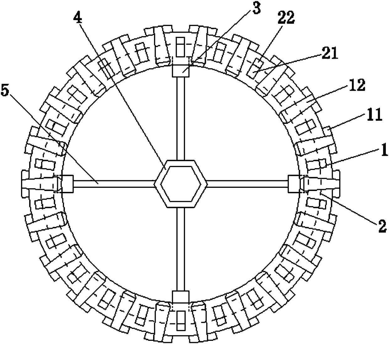
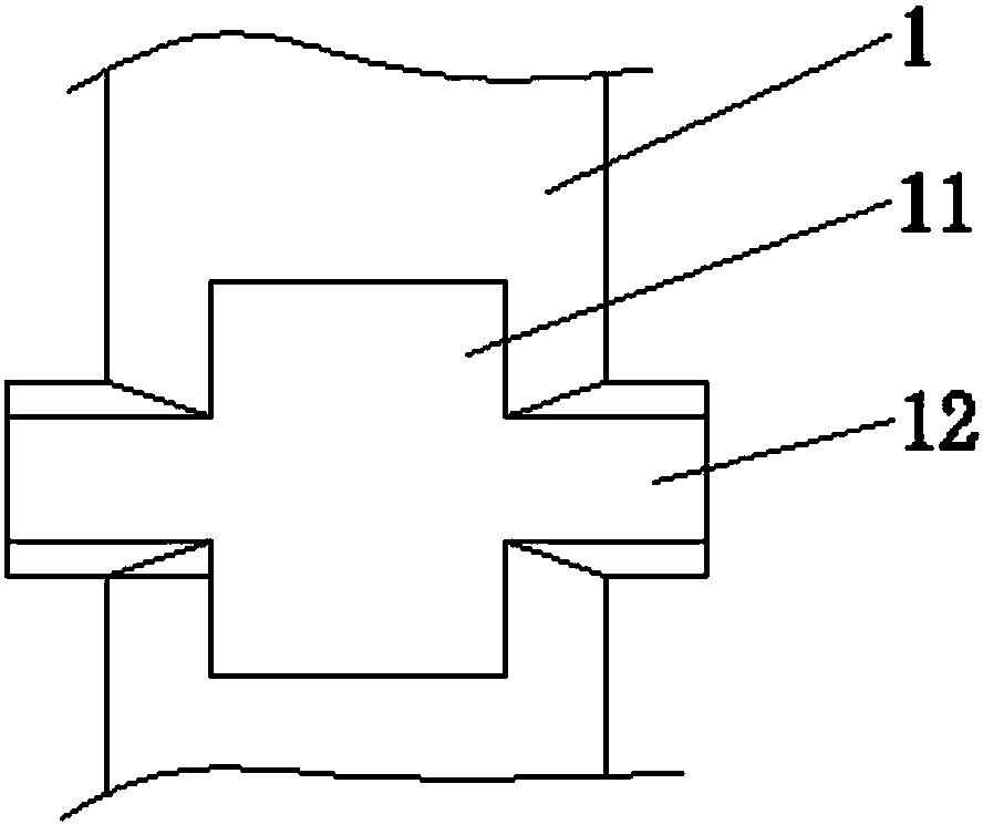
[0022] Such as figure 1 , figure 2 As shown, the road wheel rim of the tiller has a rim 1 made of rubber. The width of the rim 1 is 50-70 mm, and the specific width of the rim 1 is determined according to actual needs, and in this embodiment, it is preferably 60 mm. Radial bosses 11 are evenly distributed on the outer circumference of the rim 1, and the radial bosses 11 and the rim 1 are integrally structured. The number of the rims 1 is determined according to actual needs, as long as the gap between two adjacent radial bosses 11 The distance between radial bosses 11 along the circumferential direction can be less than the length. The outer end surface of the radial boss 11 is an arc surface, and knurls are arranged on the outer end surface of the radial boss 11. The shapes of the knurling can be various, and the center of the circle where the outer end ...


PUM


Abstract

The invention discloses a walking wheel structure for a narrow-width micro-cultivator. Radial bosses are uniformly distributed on the outer circumferential surfaces of rims, side bosses are symmetrically arranged on the two sides of the middles of the radial bosses, the rims cover a steel skeleton, reinforcing structures uniformly distributed on the circumference are arranged on the steel skeleton, the reinforcing structures are spaced apart from the radial bosses, a hub is located at the center of the rims, a plurality of spokes uniformly distributed on the circumference are arranged betweenthe hub and the rims, and the spokes are of steel tube structures. The walking wheel structure can reduce the width of the rims, reduce the rolled area of the ground, increase road holding, avoid phenomena of idling and ridge running in arable land operation, and ensure easy operation, labor saving and high tillage efficiency. In addition, the rims cover the steel skeleton in combination with thereinforcing structures to prevent deformation or damage of the rims and facilitate connection with the spokes. The walking wheel structure has good supporting strength and is durable in harsh environments such as muddy roads.

Description

technical field [0001] The invention belongs to the technical field of miniature cultivators, and in particular relates to a walking wheel structure of a narrow-width microcultivator. Background technique [0002] With the vigorous support and development of agricultural mechanization, the use of tillage machines is becoming more and more extensive. Due to the characteristics of light weight, small size, simple structure, and convenient operation, the tiller is suitable for the cultivation of sloping land and small pieces of land in the vast hilly and mountainous areas of our country, and is deeply loved by the majority of users. [0003] At present, the walking wheels of micro tillage machines generally use wide rubber wheels, which have a large contact area with the ground and are easy to compact the ground, which is not conducive to the root growth of crops. Simultaneously, the gripping effect of the traveling wheels of the existing micro tillage machine is not good, and...

Claims


Application Information

Patent Timeline
Patent Type & Authority Applications(China)
IPC IPC(8): B60B21/00B60B21/06B60B19/00
CPCB60B21/00B60B19/00B60B21/06
Inventor 陈小龙
Owner 何德珍
Why Eureka
Try Eureka