bridge crane bridge

A bridge crane and bridge frame technology, which is applied in the direction of cranes, load blocks, load suspension components, etc., can solve the problems of troublesome disassembly work, many connection ports, and potential safety hazards of lifting trolleys, so as to improve stability and safety performance, The effect of avoiding the welding process and eliminating potential safety hazards

Active Publication Date: 2020-08-28
合肥市春华起重机械有限公司
View PDF9 Cites 1 Cited by
  • Summary
  • Abstract
  • Description
  • Claims
  • Application Information

AI Technical Summary

Problems solved by technology

At present, the main girder and the end girder are generally connected by welding. Therefore, a little carelessness in the construction process will affect the overall accuracy of the bridge frame. There are many connection ports during welding and assembly, which is time-consuming and laborious. Once the bridge frame is completed, it is not needed. Its disassembly work has also become more troublesome, many workpieces will be scrapped and cannot be reused, and there are certain safety hazards when the lifting trolley runs on the track inside the main girder

Method used


Image

  • bridge crane bridge
  • bridge crane bridge

Examples


Embodiment Construction

[0015] The following will clearly and completely describe the technical solutions in the embodiments of the present invention with reference to the accompanying drawings in the embodiments of the present invention. Obviously, the described embodiments are only some of the embodiments of the present invention, not all of them. Based on the embodiments of the present invention, all other embodiments obtained by persons of ordinary skill in the art without making creative efforts belong to the protection scope of the present invention.

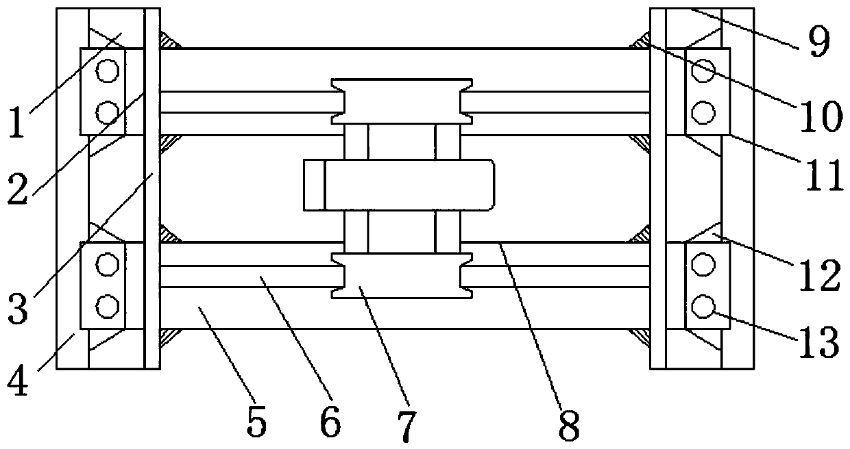
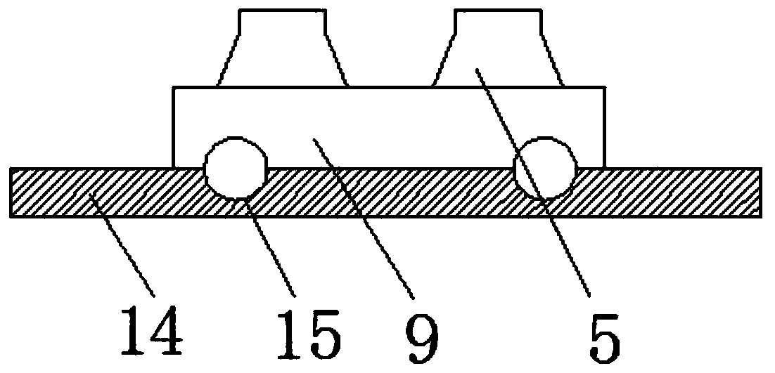
[0016] see Figure 1-2 , the present invention provides a technical solution: a bridge crane bridge, including a rectangular through hole 2, a main girder 5, an end beam 9 and a positioning plate 12, the rectangular through hole 2 is opened at both ends of the first fixed steel plate 3, The first fixed steel plate 3 is arranged on one side of the end beam 9, the other side of the end beam 9 is provided with a second fixed steel plate 4, and the i...


PUM


Abstract

The invention discloses a bridge crane loading bridge which comprises rectangular through holes, a main beam, end beams and a positioning plate. The rectangular through holes are formed in the two ends of first fixing steel plates, the first fixing steel plates are arranged on one sides of the end beams, the other sides of the end beams are provided with second fixing steel plates, the inner sidesof the second fixing steel plates are provided with limiting grooves corresponding to the rectangular through holes, a groove is formed between the inner walls of the second fixing steel plates and the first fixing steel plates, the main beam is connected between the end beams, and the two ends of the main beam penetrate through the rectangular through holes and the groove to be connected with the limiting grooves. By means of the first fixing steel plates and the second fixing steel plates, the first fixing steel plates, the second fixing steel plates and the end beams are of an integrally-formed U-shaped structure, the two ends of the main beam penetrate through the rectangular through holes to be connected with the limiting grooves in the inner sides of the second fixing steel plates,the two ends of the main beam are fixed to the positioning plate through fastening screws, the main beam can be connected with the end beams conveniently, tedious welding working procedures are avoided, the whole bridge accuracy is improved, and disassembly and assembly are convenient and fast.

Description

technical field [0001] The invention relates to the technical field of mechanical equipment, in particular to a bridge frame of a bridge crane. Background technique [0002] The bridge crane is a lifting device that is horizontally placed over the workshop, warehouse and stockyard for material lifting. Because its two ends are located on tall cement columns or metal supports, it is shaped like a bridge. The bridge frame of the bridge crane runs longitudinally along the tracks laid on the elevated sides on both sides, which can make full use of the space under the bridge frame to lift materials without being hindered by ground equipment. The structure of the bridge crane is mainly composed of a bridge running mechanism and a lifting trolley. The bridge running mechanism is mainly composed of a main beam and an end beam. The main beam and the end beam are rigidly connected. Wheels are installed at both ends of the end beam to support the bridge on the elevated There is a trac...

Claims


Application Information

Patent Timeline
Patent Type & Authority Patents(China)
IPC IPC(8): B66C6/00B66C7/00B66C11/00
CPCB66C6/00B66C7/00B66C11/00B66C2700/01
Inventor 梁大伟
Owner 合肥市春华起重机械有限公司
Why Eureka
Try Eureka