
A cooling structure for an engine bearing housing

A technology of cooling structure and bearing housing, which is applied in the direction of engine cooling, engine components, shafts and bearings, etc., and can solve problems such as weakening of lubricating oil cooling effect, bearing wear, and gas temperature rise

Active Publication Date: 2019-06-28
BEIJING POWER MACHINERY INST
View PDF11 Cites 0 Cited by
  • Summary
  • Abstract
  • Description
  • Claims
  • Application Information

AI Technical Summary

Problems solved by technology

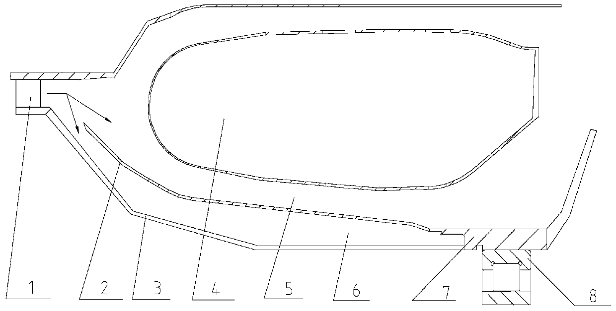
[0004] Since the airflow for cooling the bearing seat comes from the outlet of the compressor, the temperature is relatively high, so the cooling effect on the bearing seat is poor during the working process of the engine. The cylinder radiates a large amount of heat energy, and the heat energy rapidly heats the cooling gas flowing through the flame cylinder, causing the temperature of the gas to rise sharply. Such gas flows through the bearing seat, which easily causes the structure of the bearing seat to deform and increase in size
When the gap between the bearing seat and the bearing becomes larger and the contact surface twists and changes, the vibration value at this place increases accordingly; if the bearing seat is overheated, the cooling effect of the lubricating oil at the bearing will also be weakened. Excessive wear requiring frequent rework or replacement of bearing housings

Method used


Image

  • A cooling structure for an engine bearing housing
  • A cooling structure for an engine bearing housing

Examples


Embodiment Construction

[0021] In order to make the purpose, content, and advantages of the present invention clearer, the specific implementation manners of the present invention will be further described in detail below in conjunction with the accompanying drawings and embodiments.

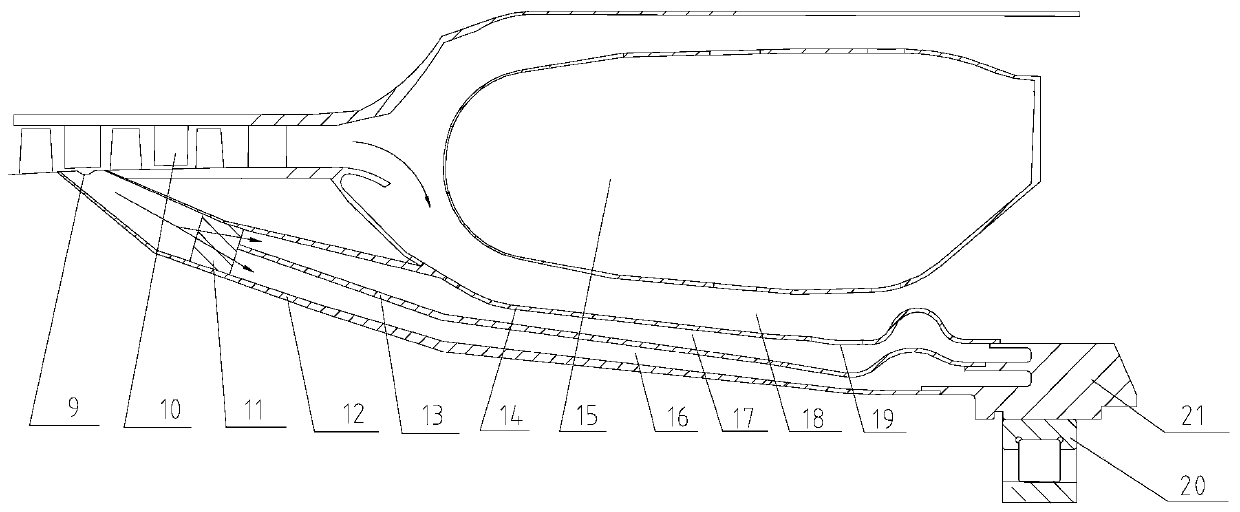
[0022] The invention proposes a structure that has a better cooling effect on the bearing seat at the hot end part of the engine. By reducing the thermal load of the bearing seat, the vibration of the bearing in the inner cavity of the bearing seat during the engine's working process is reduced, which plays a role in cooling. The purpose of protecting the bearing is to improve the working stability of the engine and prolong the service life of the bearing.

[0023] The engine bearing block cooling structure provided by the present invention is a three-layer annular structure, which includes a support plate 11, an outer partition 12, a middle partition 13, an inner partition 14 and a bearing 20, three The partition form...


PUM


Abstract

The invention relates to a cooling structure of an engine bearing block, and belongs to the field of engines. By adopting the cooling scheme of the engine bearing block, the cooling structure has theadvantages that the better cooling effect is realized for the bearing block at the heat end part of the engine; by reducing the heat load of the bearing block, the vibration of a bearing in an inner cavity of the bearing block is reduced in the working process of the engine, the purpose of protecting the bearing is realized, the working stability of the engine is improved, and the service life ofthe bearing is prolonged.

Description

technical field [0001] The invention relates to the technical field of engines, in particular to a cooling structure for engine bearing seats. Background technique [0002] The fulcrum of all the rotors in the engine is the bearing, all the loads of the engine are carried by the bearing, and the bearing seat is the support and stress point of the bearing, which bears the load force from the bearing during the working process of the engine. The structure of the bearing seat is usually compact, so it requires high stability during work. During the working process of the engine, in addition to ensuring the cooling effect of the bearing, the bearing seat also needs sufficient cooling effect, otherwise it will easily cause problems such as unstable bearing operation, large vibration, and bearing wear, which will affect the working state of the engine and even damage the engine. Therefore, in the design structure of the engine, a special cooling structure is designed for the bear...

Claims


Application Information

Patent Timeline
Patent Type & Authority Patents(China)
IPC IPC(8): F16C35/04F02C7/18
CPCF02C7/18F16C35/04
Inventor 杨凯蔡文哲党永杰李思琪王森张莉爽余海生邵伏永
Owner BEIJING POWER MACHINERY INST
Learn More