Cutting device

A technology for cutting devices and spindles, applied in textiles and papermaking, etc., can solve the problems of operator injury and high injury, and achieve the effect of saving space and reducing the risk of injury

Active Publication Date: 2018-06-08
MASCHINENFABRIK RIETER AG
View PDF6 Cites 0 Cited by
  • Summary
  • Abstract
  • Description
  • Claims
  • Application Information

AI Technical Summary

Problems solved by technology

However, having the ring on the spool is a disadvantage, i.e. each spool must be equipped with a ring, which is a not insignificant cost factor
Furth

Method used


Image

  • Cutting device
  • Cutting device
  • Cutting device

Examples


Embodiment Construction

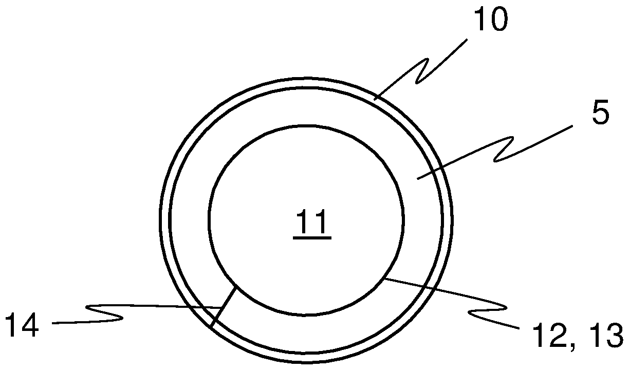
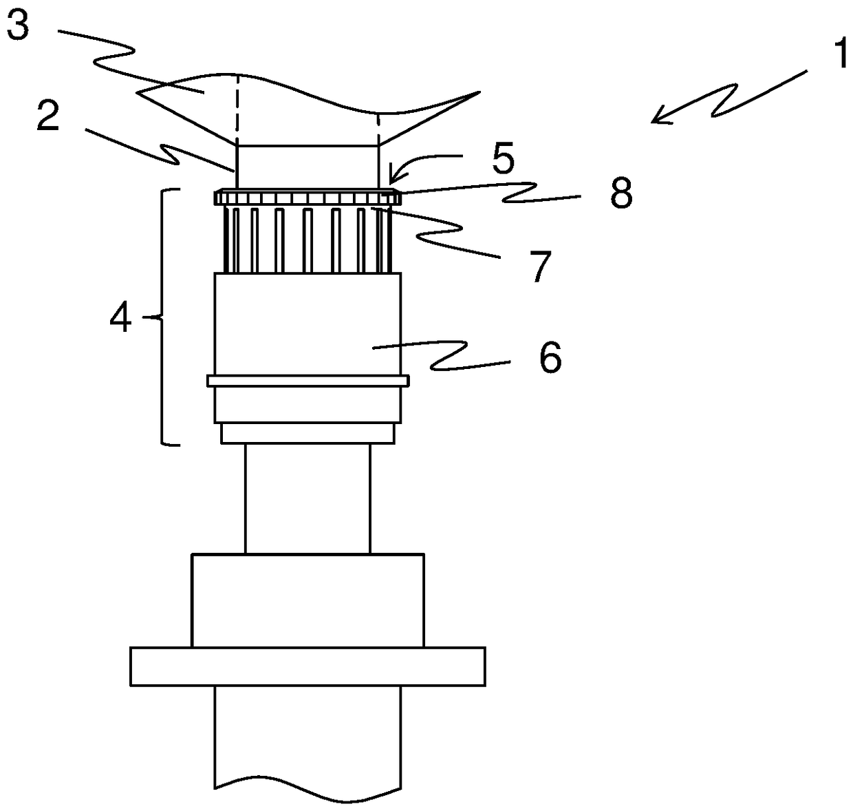
[0038] figure 1 A side view of the spindle 1 is shown. Cops 3 are located on shaft 2 of spindle 1 . Adjacent to the shaft 2 of the spindle 1 there is a clamping crown 4 . Furthermore, a cutting device 5 separate from the clamping crown is arranged on the clamping crown 4 , although it is barely visible here, but is designed flat and is located on the clamping crown 4 . Cutting means, cutting edges etc. are suitable as cutting means 5, as described in the examples below.

[0039] Figure 2a The clamping crown 4 is shown in more detail in the open state as it occurs shortly before the bobbin 3 is removed from the spindle 1 . The clamping sleeve 6 has been pulled down in the process, so that the lower winding area 7 is opened. Then, several turns of the wire are wound onto the winding lower area 7 . Between the bobbin 3 and the winding lower region 7 the thread runs through a recess in the clamping ring 8 and thus also passes the cutting device 5 .

[0040] Then, if Figu...


PUM


Abstract

The present invention relates to a spindle (1) for a workstation of a textile machine, in particular of a ring spinning machine, having a shank (2) for receiving a tube which becomes a cop (3) as theresult of a thread being wound up, and a cutting device (5, 15, 20) for cutting the thread when the cop (3) is taken off the spindle (1), wherein the cutting device (5, 15, 20) has a cutout (11) for enclosing the shank (2), an inner region (12, 24) adjoining the cutout (11), and a cutting region (10, 16, 21). According to the invention, the inner region (12, 24) of the cutting device (5, 15, 20) has at least one clamping region (13, 25) for clamping the cutting device (5, 15, 20) to the shank (2). Furthermore, the invention relates to a cutting device (5, 15, 20) for cutting a thread when a cop (3) is taken off a spindle (1).

Description

technical field [0001] The invention relates to a spindle for a workstation of a textile machine, in particular a ring spinning machine, according to the independent claims. The invention also relates to a cutting device and a ring spinning machine with a plurality of workstations. Background technique [0002] For example from EP 911 434 B1 a spindle for a ring spinning machine is known with a cutting device for cutting the spinning thread when removing the bobbin, wherein the cutting device is guided by a collar on the top of the spindle and fixed to the spindle with a protrusion On the top of the spindle, the protrusion engages behind a groove in the top of the spindle. However, this type of fastening presupposes a groove in the top of the spindle, which is known to be provided on only a few special spindles. Therefore, this cutting device cannot be used for any other spindle. [0003] EP0292856A1 discloses an upper ring with a cut-off area and a flange. This ring is ...

Claims


Application Information

Patent Timeline
IPC IPC(8): D01H9/16
CPCD01H9/16
Inventor R.纳格里
Owner MASCHINENFABRIK RIETER AG
Why Eureka
Try Eureka