Liquid crystal beam control device and manufacture

A beam control, beam technology, applied in optics, optical components, nonlinear optics, etc., can solve the problems of high manufacturing cost, poor beam intensity distribution, excessive and so on

Active Publication Date: 2018-06-08
LENSVECTOR
View PDF17 Cites 4 Cited by
  • Summary
  • Abstract
  • Description
  • Claims
  • Application Information

AI Technical Summary

Problems solved by technology

There are various problems including: limited (extended) angle control, poor (quality) beam intensity distribution, excessive color separation, high manufacturing cost, unsuitable operating voltage, etc.

Method used


Image

  • Liquid crystal beam control device and manufacture
  • Liquid crystal beam control device and manufacture
  • Liquid crystal beam control device and manufacture

Examples


Embodiment Construction

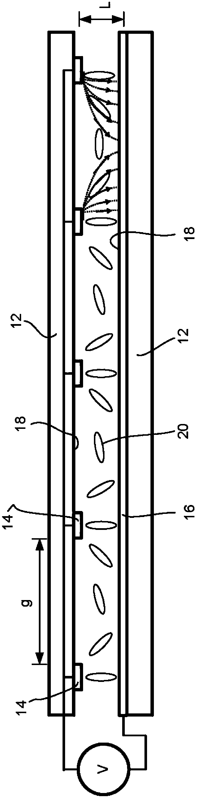
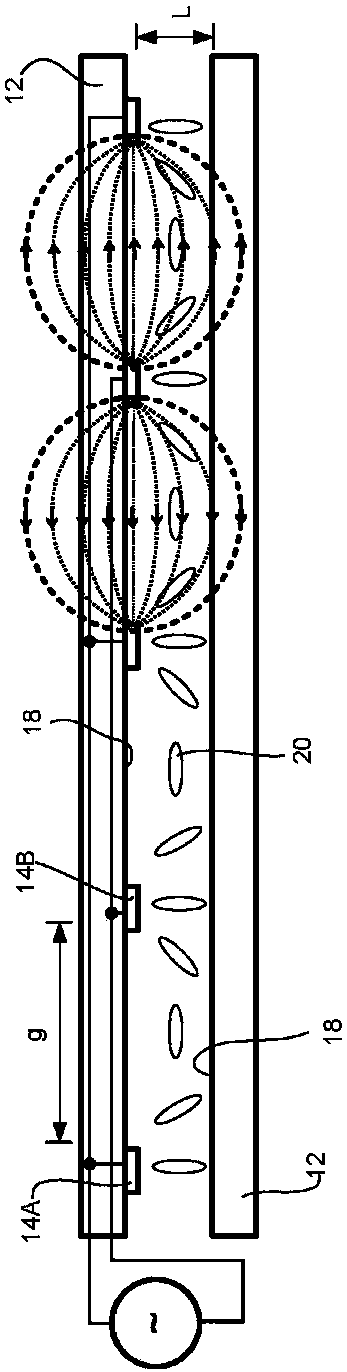
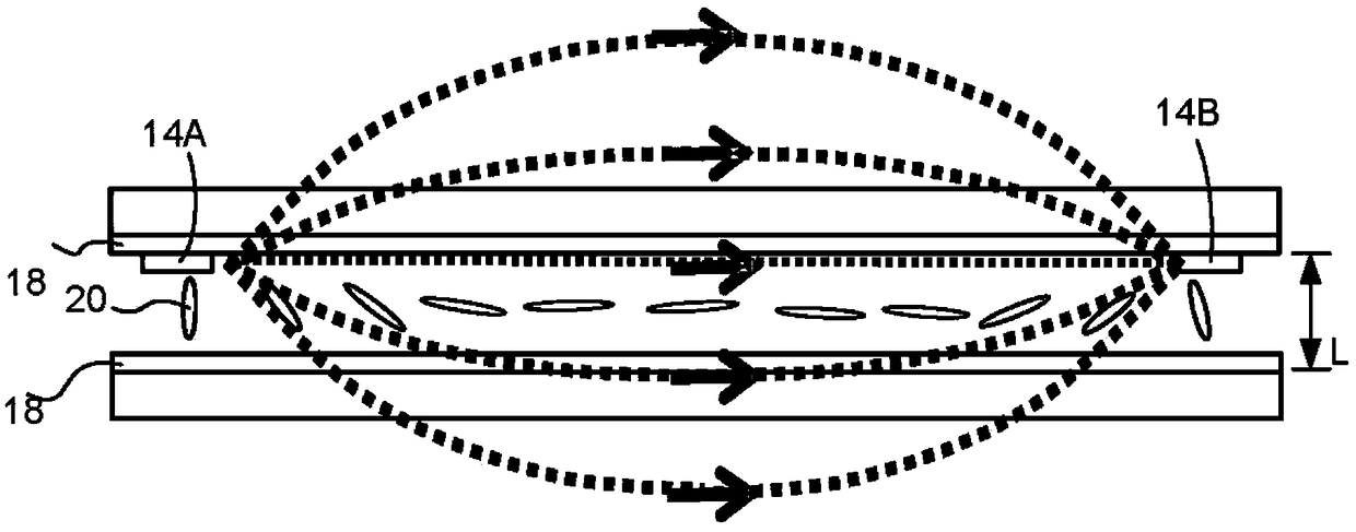
[0086] A beam steering device is an optical device that controls the (refracted) output beam of light, enabling beam divergence or direction (direction) control of said beam. Controlling beam divergence / convergence is a special case of beam steering to provide focus / defocus. Beam direction control can be used for beam steering purposes. Beam steering devices that provide a combination of beam spreading, beam divergence / convergence, or beam direction control are generally referred to herein as beam steering devices.

[0087] In liquid crystal beam steering devices, electric fields are commonly used to control the molecular orientation of liquid crystal material in an LC cell. The electric field can spatially modulate the optical aperture of the liquid crystal optics to spatially modulate the liquid crystal orientation. Changes in molecular orientation will affect the local refractive index of the LC material and can create a refractive index gradient of the LC material throug...


PUM


Abstract

Liquid crystal light beam control devices and their manufacture are described. Beneficial aspects of beam broadening devices employed for controlled illumination and architectural purposes are presented including improving beam divergence control, improving beam broadening dynamic range control, beam divergence preconditioning, improving projected beam intensity uniformity and reducing color separation in the projected beam. Both beam control devices having in-plane and homeotropic ground state liquid crystal alignment are presented.

Description

[0001] related application [0002] This patent application claims priority as: U.S. Provisional Patent Application US62 / 217,875, filed September 12, 2015; U.S. Provisional Patent Application US62 / 242,422, filed October 16, 2015, all of which are incorporated References for this article. technical field [0003] This patent application relates to a liquid crystal light beam steering device and its manufacture. Background technique [0004] Liquid crystal beam steering devices are well known in the art. Some of these devices typically use patterned electrodes on the liquid crystal cell to create spatial variations in the refractive index for beam steering. To keep the voltage low, electrodes can be placed inside or on both sides of the cell substrate. In order to improve the optical performance, the size of the adjustment element (dimensions) and / or the aspect ratio of the beam (control), mainly defined by the ratio of the height of the patterned electrode to the thickness...

Claims


Application Information

Patent Timeline
Patent Type & Authority Applications(China)
IPC IPC(8): G02B27/09G02F1/13
CPCG02F1/134309G02F1/134363G02F1/292G02F2203/06G02F2203/24G02F2203/50G02F1/133742G02F1/133504G02F1/133528G02F1/1337G02F1/13439G02F2201/122G02F2203/26
Inventor 弗拉底米尔·普雷尼亚科夫卡伦·阿萨特里安阿尔门·佐哈拉拜亚恩迪格兰·加尔斯蒂安阿拉姆·巴格拉姆亚恩西蒙·卡罗
Owner LENSVECTOR
Why Eureka
Try Eureka