Piezoelectric transformer

A piezoelectric transformer and transformer technology, applied in the field of piezoelectric transformers, can solve the problems of increasing the loss of piezoelectric components, and achieve the effect of reducing the input capacitance

Active Publication Date: 2018-06-08
EPCOS AG
View PDF14 Cites 2 Cited by
  • Summary
  • Abstract
  • Description
  • Claims
  • Application Information

AI Technical Summary

Problems solved by technology

However, outside the maximum efficiency range, the

Method used


Image

  • Piezoelectric transformer
  • Piezoelectric transformer
  • Piezoelectric transformer

Examples


Embodiment Construction

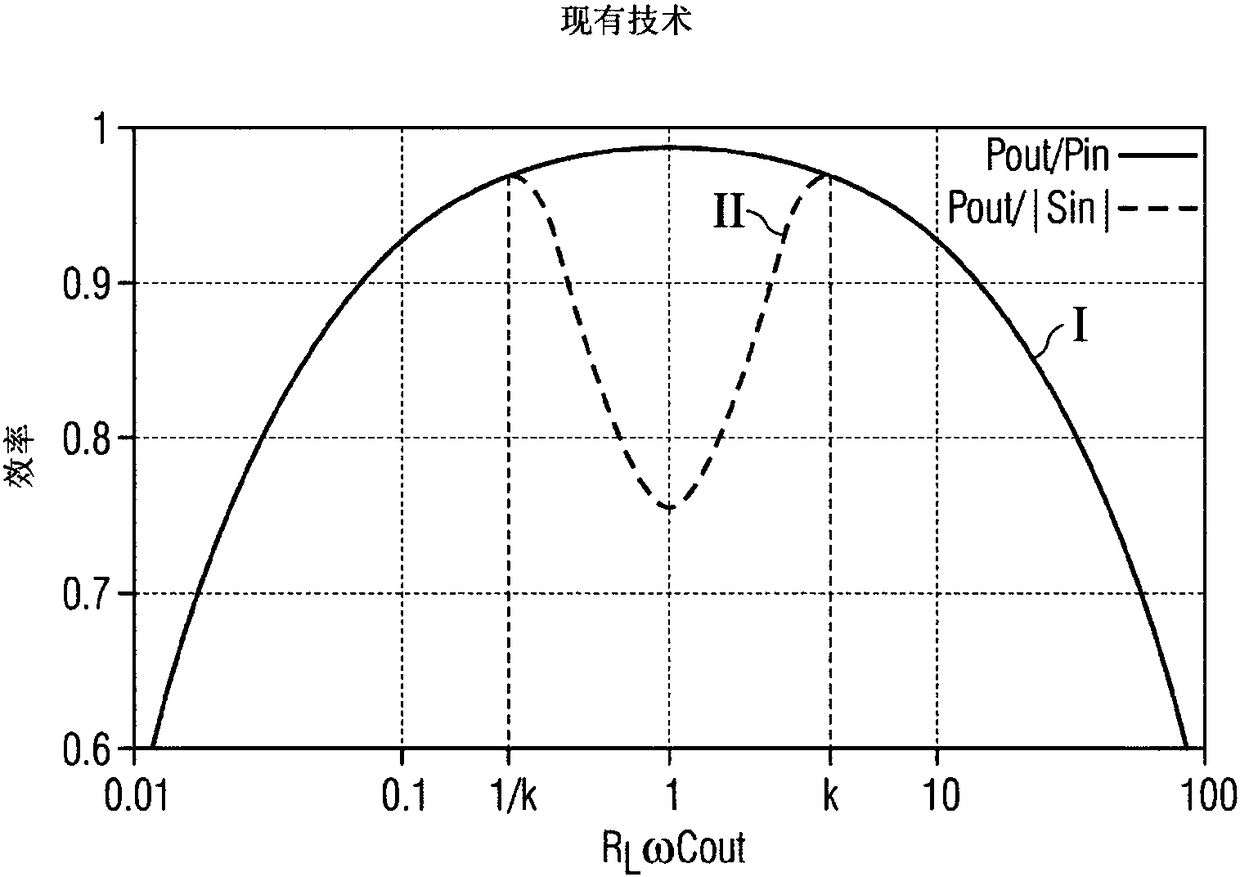
[0038] figure 1 has been discussed in detail above, and similarly, according to Figure 5 The equivalent circuit diagram of the piezoelectric transformer is also discussed in detail above.

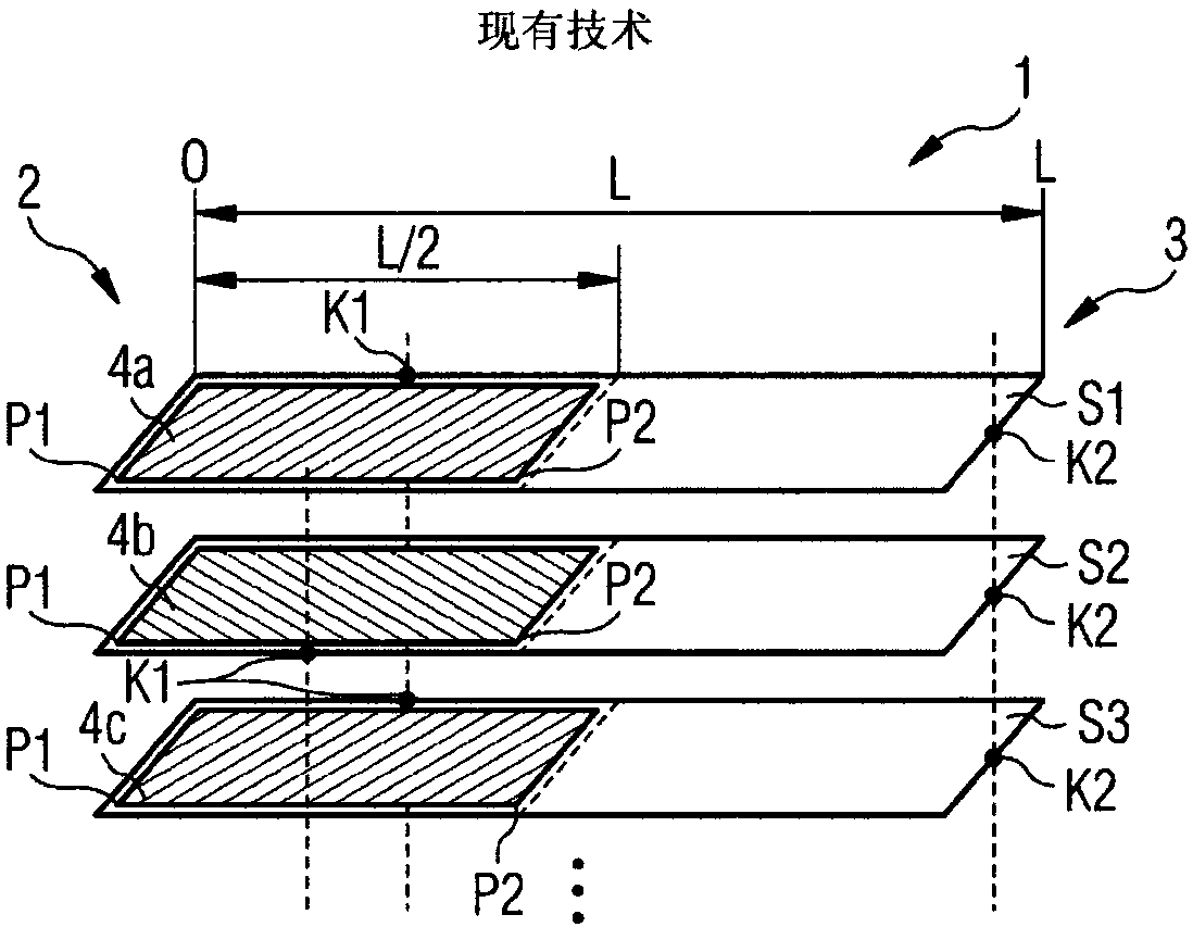
[0039] figure 2 A schematic diagram showing the layer structure of parts of a piezoelectric transformer according to the prior art. The transformer includes a piezoelectric element 1 having a predetermined length dimension of length L defined from the left side (length=0) to the right side (length=L). The piezoelectric element 1 has an input side 2 and an output side 3 . The outer end of output side 3 can be metallized, for example, and form an output electrode. The input side 2 extends on the left side of the piezoelectric element 1 in the range of 0 to 1 / 2L of the length dimension. The output side 3 extends in the range of 1 / 2L to L of the length dimension on the right side of the piezoelectric element 1 .

[0040] The piezoelectric element 1 is constructed in a multi-layer constr...


PUM


Abstract

The invention relates to a piezoelectric transformer comprising a piezoelectric element (1) of length L, wherein an input voltage Uin can be applied at an input side (2) for transformation into an output voltage Uout at an output side (3) according to a transformation ratio formula (I). The piezoelectric element (1) has multiple plies (4a, 4b, 4c) of inner electrodes, which are arranged in multiple different layers (S1, S2, S3). Each ply (4a, 4b, 4c) of inner electrodes extends along at least one predetermined sub-section of a predetermined length, wherein sub-sections of plies (4a, 4c) of a first group of layers (S1, S3) and sub-sections of plies (4b) of a second group of layers (S2) have different dimensions, such that the piezoelectric transformer satisfies the following condition: Cin<=N2Cout, wherein Cin represents the input capacity, Cout represents the output capacity and N represents the transformation ratio of the ideal transformer.

Description

technical field [0001] The invention relates to a piezoelectric transformer comprising a piezoelectric element having a predetermined length dimension of length L along which at least one input side and at least one output side of the transformer are defined. The input voltage U can be applied on the input side in , according to the transformation ratio U out / U in =K u Converted on the output side to the output voltage U out . The piezoelectric element here has a plurality of plies of internal electrodes which are arranged in a plurality of different layers along a direction which is perpendicular to the direction of the length dimension. Background technique [0002] Such piezoelectric transformers are often used for voltage conversion. The impedance of such a piezotransformer is reached at a particular resonant frequency when the load on the output side corresponds to the impedance of the output capacitance of the piezotransformer (capacitance between the area of ​​...

Claims


Application Information

Patent Timeline
IPC IPC(8): H01L41/047H01L41/107
CPCH10N30/871H10N30/40H10N30/045H10N30/06H10N30/50H10N30/804
Inventor 迈克尔·韦尔古尼弗朗茨·林纳
Owner EPCOS AG
Why Eureka
Try Eureka