Yarn splicing device

A technology of splicing device and yarn, applied in the direction of piecing device, spinning machine, transportation and packaging, etc., can solve the problems of large installation space, unavailability, huge yarn splicing device, etc., and achieve the effect of compact structure

Inactive Publication Date: 2018-06-12
SAURER GERMANY GMBH & CO KG
View PDF6 Cites 2 Cited by
  • Summary
  • Abstract
  • Description
  • Claims
  • Application Information

AI Technical Summary

Problems solved by technology

[0011] Although the above-described yarn splicing devices generally equipped with pivotally mounted closure elements have proven themselves in practice, these yarn splicing devices have the disadvantage that such yarn splicing devices are usually relatively bulky
That is to say, especially due to the pivotally mounted cover, such yarn splicing devices generally require a large installation space, which is known to be generally not available in the working area of ​​automatic winding machines

Method used


Image

  • Yarn splicing device
  • Yarn splicing device
  • Yarn splicing device

Examples


Embodiment Construction

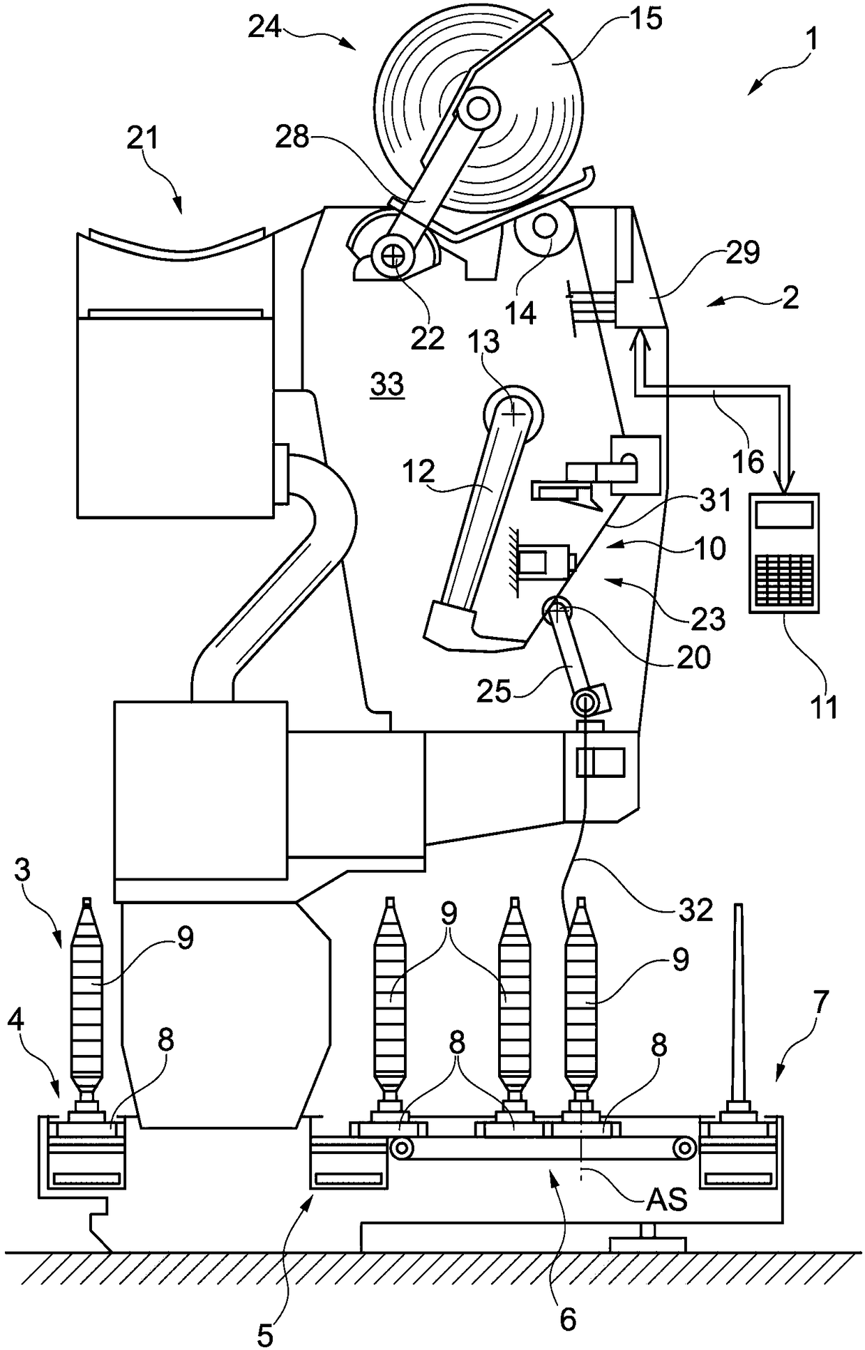
[0037] figure 1 Shown is a schematic side view of a workstation 2 of a textile machine in an embodiment of an automatic winder 1 producing cross-wound packages.

[0038] Such an automatic winding machine 1 has a plurality of workstations 2 of the same type, which are arranged next to each other in a row.

[0039] At said workstation 2, the unwinding package 9 (such as a spool produced on a ring spinning machine) is rewound into a bulky cross-wound package 15, after which the cross-wound package 15 is completed, It is delivered by an automated service unit to a cross-wound package conveyor 21 along the full length of the machine and from there to a package loading station arranged at the end of the machine.

[0040] In this embodiment, the automatic winder 1 is equipped with its own logistics device in the form of a bobbin and empty tube delivery system 3, in which figure 1 Only the spool supply line 4 , the reversibly driven storage line 5 , one of the transverse transfer li...


PUM


Abstract

The invention relates to a yarn splicing device (10) which is used for pneumatically for splicing two yarn ends. The yarn splicing device comprises a splicing prism (23) which has a splicing channel (41). Compressed air can be added into the splicing channel (41). The splicing channel (41) can be closed by a cover (18) in a splicing operation period. According to the yarn splicing device, the cover (18) is slidably mounted and can be arranged, through a driving device (44), in a manner that the cover (18) is fixed to a position (I) which is open in an upward direction in the splicing channel (41) of the splicing prism (23) or a position that is closed in the upward direction in the splicing channel (41).

Description

technical field [0001] The invention relates to a yarn splicing device for pneumatically joining two yarn ends comprising a splicing prism having a splicing channel to which compressed air can be applied and which can be covered during the splicing operation The file is closed. Background technique [0002] Yarn splicing devices for automatic winding machines have been known for a long time from numerous patent applications as well as from the manuals of various textile machine manufacturers. [0003] In the case of two yarn splicing devices, the splicing channel of the so-called splicing prism remains open during the splicing operation, compressed air can be applied to the splicing channel, and in the case of the yarn splicing device, the splicing channel is spliced ​​during the splicing operation It is known that the channels are closed by special covers. [0004] For example, DE3935536C2 describes a yarn splicing device equipped with a splicing prism whose splicing chan...

Claims


Application Information

Patent Timeline
Patent Type & Authority Applications(China)
IPC IPC(8): B65H69/06
CPCB65H69/06B65H2701/31D01H15/00
Inventor S·斯查顿
Owner SAURER GERMANY GMBH & CO KG
Why Eureka
Try Eureka