Blade Lifting Equipment and Blade Lifting Systems

A technology for hoisting equipment and blades, which is applied in the directions of transportation and packaging, and load hanging components, etc., which can solve the problems of short operation time, difficulty in impeller assembly, and poor versatility, so as to reduce assembly difficulty and assembly cost, reduce The effect of hoisting waiting time and increasing operable time

Active Publication Date: 2019-10-08
JIANGSU GOLDWIND SCI & TECH CO LTD
View PDF5 Cites 1 Cited by
  • Summary
  • Abstract
  • Description
  • Claims
  • Application Information

AI Technical Summary

Problems solved by technology

If the lifting lugs are arranged directly on the hub, since the hub needs to bear the load of the entire impeller, and the lifting lugs and the hub are cast in one piece, the structural requirements for the hub are relatively high, and some types of hubs do not have a setting position for lifting lugs. Therefore, the scope of application of the lifting method will also be reduced
In addition, if the lifting point is arranged on the variable pitch bearing or the hub, it is necessary to design a hanger matching the lifting lug, which will increase the difficulty of hub design and reduce the mechanical properties of the hub, and the versatility is not strong
In addition, the above-mentioned hoisting device also has the problems of using the first hoisting device, that is, during the process of turning over the impeller or adjusting the angle, the straps are severely worn and the hoisting efficiency is low.
[0009] In addition, the overall hoisting method of the impeller, because the overall area of ​​the impeller is relatively large, it is difficult to assemble the impeller at operating sites such as ship decks, mountains or forests, or even impossible to install. At the same time, when the entire impeller is hoisted in the air , less time to operate, and less efficient assembly

Method used


Image

  • Blade Lifting Equipment and Blade Lifting Systems
  • Blade Lifting Equipment and Blade Lifting Systems

Examples


Embodiment Construction

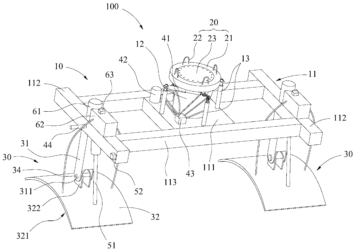
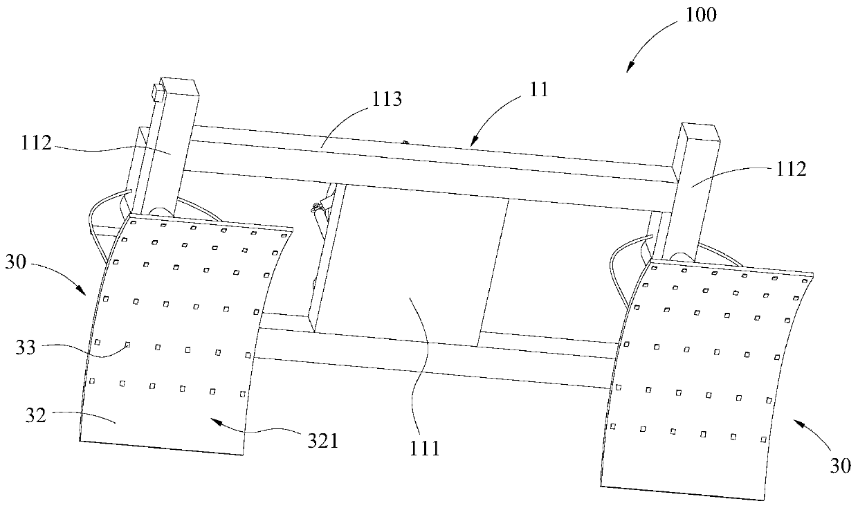
[0042] Features and exemplary embodiments of various aspects of the invention will be described in detail below. In the following detailed description, numerous specific details are set forth in order to provide a thorough understanding of the present invention. It will be apparent, however, to one skilled in the art that the present invention may be practiced without some of these specific details. In the drawings and the following description, at least some well-known structures and techniques have not been shown in order to avoid unnecessarily obscuring the present invention; and, for clarity, the dimensions of some structures may have been exaggerated. The same reference numerals in the drawings denote the same or similar structures, and thus their detailed descriptions will be omitted. Furthermore, the features, structures, or characteristics described hereinafter may be combined in any suitable manner in one or more embodiments.

[0043] The orientation words appearing...


PUM


Abstract

The invention provides a blade hoisting device and a blade hoisting system. The blade hoisting device comprises a bearing main body and a blade sucking device. The blade sucking device comprises a keeping component and a sucking connecting piece. The keeping component is connected with the bearing main body, the sucking connecting piece is arranged on the side, away from the bearing main body, ofthe keeping component, and the blade sucking device can suck blades to be assembled through sucking force produced by the sucking connecting piece. The impeller assembling process can be simplified, the assembling difficulty and cost can be reduced, and meanwhile impeller assembling efficiency is improved.

Description

technical field [0001] The invention relates to the technical field of wind power generation, in particular to a blade hoisting device and a blade hoisting system. Background technique [0002] As an important part of the wind turbine, the impeller is a crucial factor affecting the power generation of the wind turbine. During the installation of the wind turbine, the tower is usually fixed first, and the nacelle is fixed on the top of the tower. , and then lift the impeller of the wind turbine. When installing the impeller, it is necessary to ensure that the flange surface of the main shaft is parallel to the flange surface of the hub of the impeller, so as to realize the docking of the impeller and the main shaft and the installation operation of each connecting piece. [0003] However, during the assembly process of the impeller, generally when the hub of the impeller is hoisted to a corresponding installation position aligned with the main shaft, there inevitably exists ...

Claims


Application Information

Patent Timeline
Patent Type & Authority Patents(China)
IPC IPC(8): B66C1/02
Inventor 沈星星张新刚张竹李晔
Owner JIANGSU GOLDWIND SCI & TECH CO LTD
Why Eureka
Try Eureka