
Portal crane provided with hydraulic lifting platform and capable of realizing automatic dust collection

A technology of hydraulic lifting platform and gantry crane, which is applied in the direction of trolley cranes, cranes, cleaning methods using gas flow, etc., which can solve the problems of inconvenient use, large shaking, and affecting the walking of rollers, so as to ensure the service life and facilitate cleaning , the effect of simple structure

Inactive Publication Date: 2018-06-12
合肥市春华起重机械有限公司
View PDF6 Cites 2 Cited by
  • Summary
  • Abstract
  • Description
  • Claims
  • Application Information

AI Technical Summary

Problems solved by technology

[0003] However, most of the gantry cranes currently on the market have relatively simple functions and are very inconvenient to use. When the traditional gantry cranes are used, the electric hoist wire rope is relatively soft and shakes greatly during operation, which is not conducive to scientific research. After use, the dust will also affect the walking of the rollers on the main beam, which needs to be cleaned regularly, which is very inconvenient and not suitable for mass production

Method used


Image

  • Portal crane provided with hydraulic lifting platform and capable of realizing automatic dust collection
  • Portal crane provided with hydraulic lifting platform and capable of realizing automatic dust collection
  • Portal crane provided with hydraulic lifting platform and capable of realizing automatic dust collection

Examples


Embodiment Construction

[0020] In order to make the technical means, creative features, goals and effects achieved by the present invention easy to understand, the present invention will be further described below in conjunction with specific embodiments.

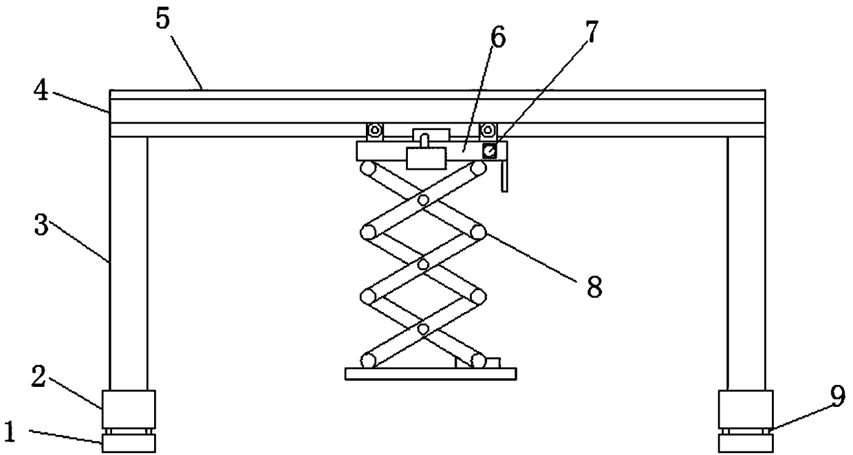
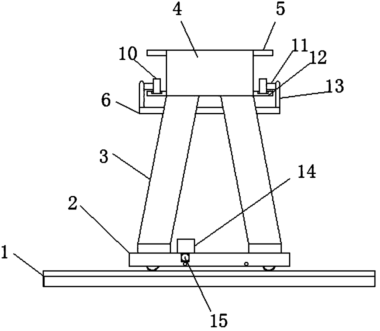
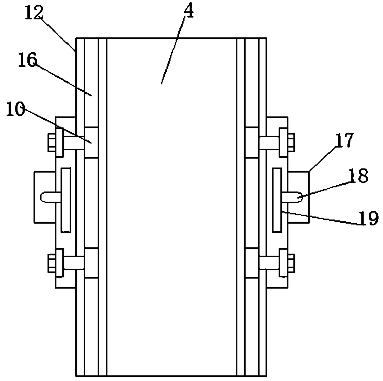
[0021] like Figure 1-4 As shown, a hydraulic lifting platform gantry crane capable of automatic dust removal includes a track 1, a lower beam 2, legs 3 and a main beam 4, the lower beam 2 is located above the track 1, and the legs 3 are located on the lower beam 2. The upper end is fixedly connected. The main beam 4 is located at the upper end of the support leg 3 and is fixedly connected. Both sides of the main beam 4 are fixedly connected with a rainproof cover 5 and a support plate 12, and the support plate 12 is located on the rainproof cover Below the plate 5, a slide rail 16 is provided on the upper surface of the support plate 12, and the upper end of the slide rail 16 is rollingly connected with a roller 10. One end of the roller 10 is pr...


PUM


Abstract

The invention discloses a portal crane provided with a hydraulic lifting platform and capable of realizing automatic dust collection. The portal crane comprises rails, lower crossbeams, supporting legs and a main beam; each lower crossbeam is arranged above the corresponding rail; each supporting leg is positioned at the upper end of the corresponding lower crossbeam and is fixedly connected withthe upper end of the corresponding lower crossbeam; the main beam is positioned on the upper ends of the supporting legs and is fixedly connected with the upper ends of the supporting legs; the two sides of the main beam are each fixedly connected with a rainproof cover plate and a supporting plate; and each supporting plate is positioned below the corresponding rainproof cover plate. The portal crane disclosed by the invention is equipped with the hydraulic lifting platform and has the advantage that the hydraulic lifting platform runs in a manner of being suspended below the main beam, and small shake is generated in a lifting process, so the hydraulic lifting platform is beneficial for being used for scientific research; each rainproof cover plate which is installed can be used for preventing rain and dust from directly dropping on the corresponding supporting plate so that influences, acting on sliding rails, of the rain are prevented, and normal walking of idler wheels is not affected; a dustproof box which is installed can be used for removing the dust on the rails so that dust accumulation is prevented so as not to affect the normal walking of the idler wheels; and meanwhile, the portal crane is convenient to clean by people, simple in structure and suitable for large-batch production and application.

Description

technical field [0001] The invention relates to a gantry crane, in particular to a gantry crane with a hydraulic lifting platform capable of automatic dust removal. Background technique [0002] Gantry crane is a deformation of bridge crane, also called gantry crane. It is mainly used for loading and unloading operations of outdoor cargo yards, stockyard cargoes, and bulk cargoes. The gantry crane has the characteristics of high site utilization rate, large operation range, wide adaptability, and strong versatility. It is widely used in port freight yards. Its metal structure is like a door-shaped frame. Two legs are installed under the main beam, which can be directly Walking on the track on the ground, the two ends of the main beam can have outrigger cantilever beams. [0003] However, most of the gantry cranes currently on the market have relatively simple functions and are very inconvenient to use. When the traditional gantry cranes are used, the electric hoist wire ro...

Claims


Application Information

Patent Timeline
IPC IPC(8): B66C19/00B66C13/40B66C13/06B66C9/14B08B5/04B08B17/02
CPCB66C19/00B08B5/04B08B17/02B66C9/14B66C13/06B66C13/40
Inventor 梁大伟
Owner 合肥市春华起重机械有限公司
Learn More