Air source heat pump control method and device and system and air source heat pump

An air source heat pump and control method technology, applied in the control of air source heat pump, the field of air source heat pump, can solve the problems of poor stability, heavy grid burden, not considering the peak and valley of power consumption of the grid system, etc., to achieve the effect of improving stability

Active Publication Date: 2018-06-12
STATE GRID BEIJING ELECTRIC POWER +2
View PDF24 Cites 14 Cited by
  • Summary
  • Abstract
  • Description
  • Claims
  • Application Information

AI Technical Summary

Problems solved by technology

[0010] Embodiments of the present invention provide an air source heat pump control method, device and system, and the air source heat pump, to at least solve the problem that the control scheme for the air source heat pump in the prior art does not consider the power consumption peaks and valleys of the power grid system, resulting in a heavy load on the power grid. , technical problems of poor stability

Method used


Image

  • Air source heat pump control method and device and system and air source heat pump
  • Air source heat pump control method and device and system and air source heat pump
  • Air source heat pump control method and device and system and air source heat pump

Examples


Embodiment 1

[0027] According to an embodiment of the present invention, an embodiment of a control method for an air source heat pump is provided. It should be noted that the steps shown in the flow chart of the accompanying drawings can be executed in a computer system such as a set of computer-executable instructions, and , although a logical order is shown in the flowcharts, in some cases the steps shown or described may be performed in an order different from that shown or described herein.

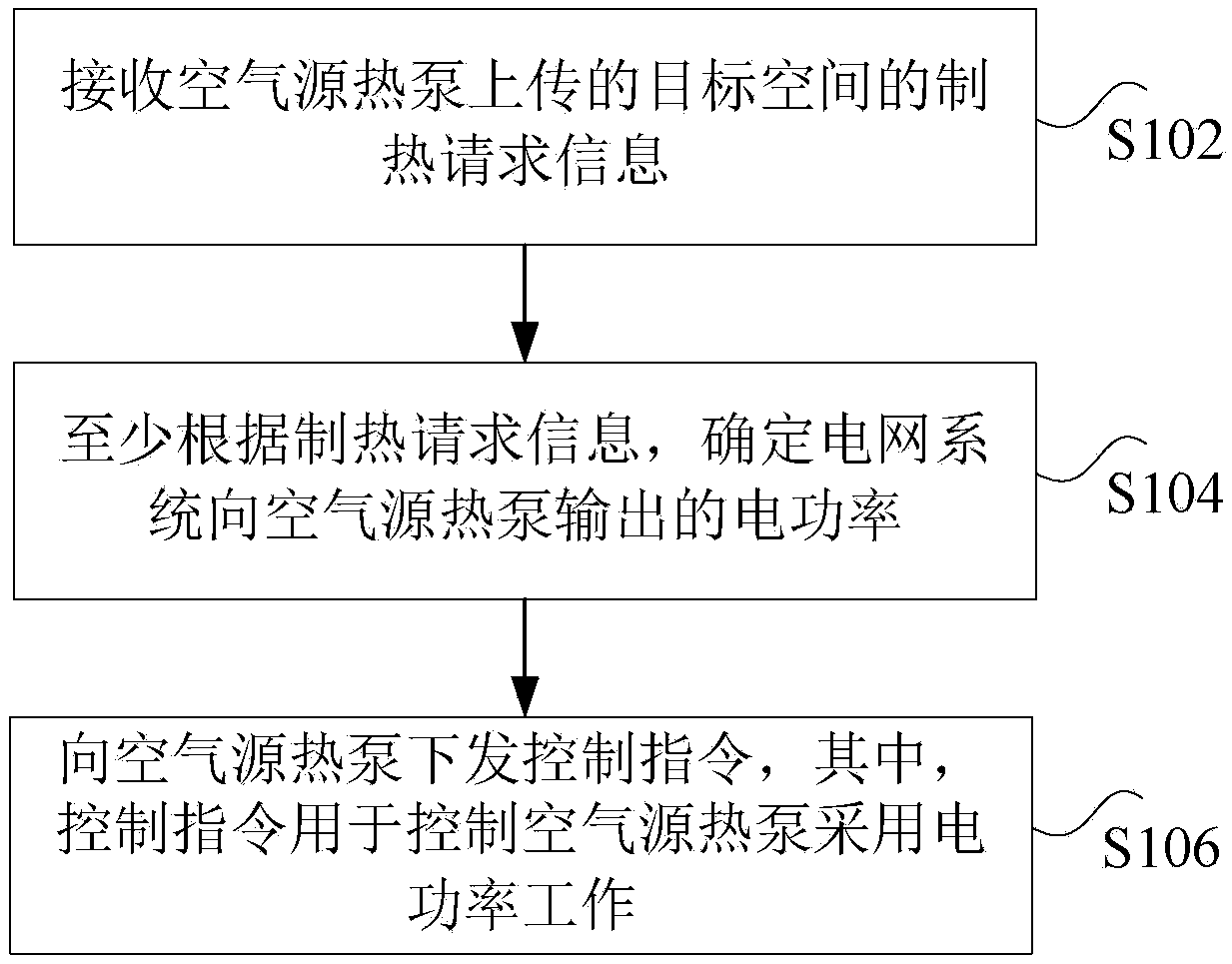
[0028] figure 1It is a flow chart of a control method of an air source heat pump according to an embodiment of the present invention, such as figure 1 As shown, the method includes the following steps:

[0029] Step S102, receiving the heating request information of the target space uploaded by the air source heat pump, wherein the target space is an indoor space heated and heated by the air source heat pump.

[0030] As an optional embodiment, the above-mentioned air source heat pump can be a ...

Embodiment 2

[0091] According to an embodiment of the present invention, a system embodiment for realizing the control method of the above-mentioned air source heat pump is also provided, Figure 4 It is a schematic diagram of a control system of an air source heat pump according to an embodiment of the present invention, such as Figure 4 As shown, the system includes: an air source heat pump 401 , a grid system 403 and a grid heating platform 405 .

[0092] Wherein, the air source heat pump 401 is used for uploading the heating request information of the target space, wherein the target space is an indoor space heated by the air source heat pump;

[0093] The power grid system 403 is connected to the air source heat pump through the public power grid, and is used to supply power for the air source heat pump;

[0094] The grid heating platform 405 communicates with the air source heat pump and the grid system respectively, and is used to receive the heating request information of the tar...

Embodiment 3

[0100] According to an embodiment of the present invention, an embodiment of an air source heat pump is also provided, Figure 6 is a schematic diagram of an air source heat pump according to an embodiment of the present invention, such as Figure 6 As shown, the air source heat pump 60 includes: a compressor 601 and a controller 603 .

[0101] Wherein, the compressor 601 is connected to the gateway, and is used to upload the heating request information of the target space to the grid heating platform through the gateway, wherein the target space is an indoor space heated by an air source heat pump;

[0102] A controller 603, configured to control the working parameters of the air source heat pump, wherein the working parameters at least include: a heating coefficient and a target temperature;

[0103] Among them, the grid heating platform is used to receive heating request information, and at least according to the heating request information, determine the electric power ou...


PUM


Abstract

The invention discloses an air source heat pump control method and device and system and an air source heat pump. The air source heat pump control method includes the steps that a heating request message of target space uploaded by the air source heat pump is received, wherein, the target space is indoor space adopting the air source heat pump to produce heat and supply heat; at least according tothe heating request message, the air source heat pump electric power output by a network system can be determined; a control instruction is transmitted to the air source heat pump, wherein, the control instruction is used for controlling the air source heat pump to adopt the electric power to operate. According to the air source heat pump control method and device and system and the air source heat pump, the technical problems in the prior art that a control scheme of the air source heat pump leaves out of consideration of electricity utilization peak valley, and the heavy burden and the badstability of a power network occur are solved.

Description

technical field [0001] The invention relates to the field of electric appliance control, in particular to a control method, device and system for an air source heat pump and the air source heat pump. Background technique [0002] Renewable energy is the material basis for the survival and development of human society. As a large energy-consuming country, China has a large population and relatively scarce energy. Although the total amount of natural resources ranks seventh in the world, the total amount of energy is about 4 trillion tons Coal ranks third in the world, and the per capita energy share is about 40% of the world average. Although my country's per capita energy consumption is less than half of the world's average per capita energy consumption, its total energy consumption has reached the second place in the world. From the perspective of energy consumption structure, my country is the largest coal consumer in the world, and coal consumption accounts for about 67%...

Claims


Application Information

Patent Timeline
Patent Type & Authority Applications(China)
IPC IPC(8): F24D19/10
CPCF24D19/10F24D2200/123F24H15/277F24H15/375F24H15/144F24H15/254F24H15/258F24H15/414
Inventor 朱洁陈平张雅静张宝群宫成丁屹峰李香龙井天军龙国标孙钦斐王钊陈海洋陈艳霞杨烁徐蕙杨建华
Owner STATE GRID BEIJING ELECTRIC POWER
Why Eureka
Try Eureka