Wind measurement method of anemometer tower and wind shadow resistant anemometer tower
A technology for wind measuring towers and tower tubes, applied in the direction of measuring devices, speed/acceleration/impact measurement, instruments, etc., can solve the problem that wind measuring instruments cannot accurately detect wind force, wind direction, etc., and achieve suitable popularization and use, simple structure and high effect significant effect
- Summary
- Abstract
- Description
- Claims
- Application Information
AI Technical Summary
Problems solved by technology
Method used
Image
Examples
Embodiment 1
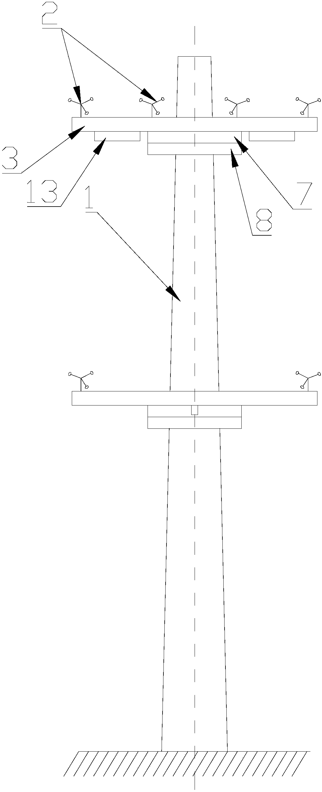
[0045] Such as figure 1 , Figure 6 and Figure 7As shown, this implementation introduces a wind-shadow resistant wind-measuring tower, which includes a tower tube 1 vertically arranged on the ground, and at least one height on the tower tube 1 is provided with a wind-measuring platform 3 arranged horizontally. At least one set of anemometer 2 is installed on the wind platform 3, and the wind measuring platform 3 is connected to the tower 1 through a rotatable hinge, and the wind measuring platform 3 is also fixedly installed with a vertically arranged baffle in the radial direction. The horizontal extension axis of the windshield 13 and the windshield 13 are set perpendicular to the connecting line between the anemometer 2 and the axis of the tower 1, so that the windshield 13 drives the wind measuring platform 3 to rotate around the tower body under the wind force to The wind instrument 2 is in a direction perpendicular to the wind direction relative to the tower tube 1 ....
Embodiment 2
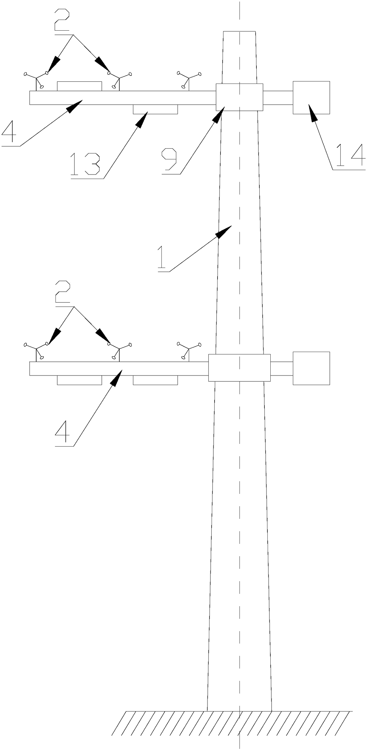
[0058] Such as figure 2 , Figure 8 and Figure 9 As shown, in this embodiment, a wind-shadow-resistant wind-measuring tower is introduced, including a tower tube 1 vertically arranged on the ground, at least one height surface of the tower tube 1 is a wind-measuring plane, and the wind-measuring plane is set on the opposite At least two anemometers 2 arranged symmetrically on the axis of the tower 1, each anemometer 2 includes a support rod 15, the lower end of the support rod 15 is fixedly connected to the tower 1, and the upper end of the support rod 15 is provided with a support rod 15. A tripod that rotates about the axis. The tripod is provided with at least three wind measuring bowls 16 that are symmetrically arranged relative to the axis of the support rod 15.
[0059] By setting at least two anemometers in the same height plane of the tower, the wind force and wind direction in multiple directions around the tower can be detected to increase the diversity of data c...
Embodiment 3
[0069] This embodiment introduces a wind measurement method based on the wind shadow resistance wind measuring tower in the second embodiment above. At least two wind measuring points arranged at the same distance from the wind measuring tower are used to measure wind direction and wind force, and the wind force and wind direction values measured at the two wind measuring points are combined to obtain the actual measured wind force and wind direction .
[0070] By detecting the wind force and wind direction at different positions on the wind measuring height surface, and obtaining the actual measured wind force and wind direction according to the detected value, the actual measured value integrates the measured values of all directions of the tower, making the measurement result more accurate. The influence of tower wind shadow on measurement results is reduced.
[0071] In this embodiment, the specific steps of wind force measurement are as follows,
[0072] Step 11), r...
PUM
 Abstract
Description
Claims
Application Information
 - R&D
- Intellectual Property
- Life Sciences
- Materials
- Tech Scout
- Unparalleled Data Quality
- Higher Quality Content
- 60% Fewer Hallucinations
Browse by: Latest US Patents, China's latest patents, Technical Efficacy Thesaurus, Application Domain, Technology Topic, Popular Technical Reports.
© 2025 PatSnap. All rights reserved.Legal|Privacy policy|Modern Slavery Act Transparency Statement|Sitemap|About US| Contact US: help@patsnap.com


