Structure of high-precision reflector antenna composite panel and adjustment method thereof

A technology of antenna combination and reflective surface, which is applied in the direction of antennas and electrical components, can solve the problems of poor alignment of rigid connection standard parts, low efficiency, inability to coordinate the linkage of combined panel components, high-precision adjustment, etc., to eliminate Curved, good neutrality, and the effect of improving adjustment efficiency

Pending Publication Date: 2018-06-12
NO 54 INST OF CHINA ELECTRONICS SCI & TECH GRP
View PDF0 Cites 10 Cited by
  • Summary
  • Abstract
  • Description
  • Claims
  • Application Information

AI Technical Summary

Problems solved by technology

[0004] 1. There is only one-stage adjustment, and the efficiency is extremely low;
[0005] 2. The linkage and high-precision adj

Method used


Image

  • Structure of high-precision reflector antenna composite panel and adjustment method thereof
  • Structure of high-precision reflector antenna composite panel and adjustment method thereof
  • Structure of high-precision reflector antenna composite panel and adjustment method thereof

Examples


Embodiment 1

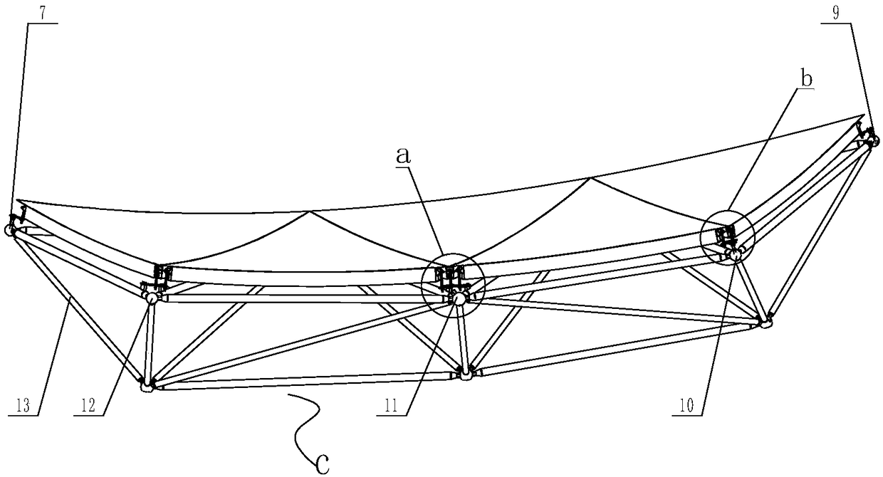
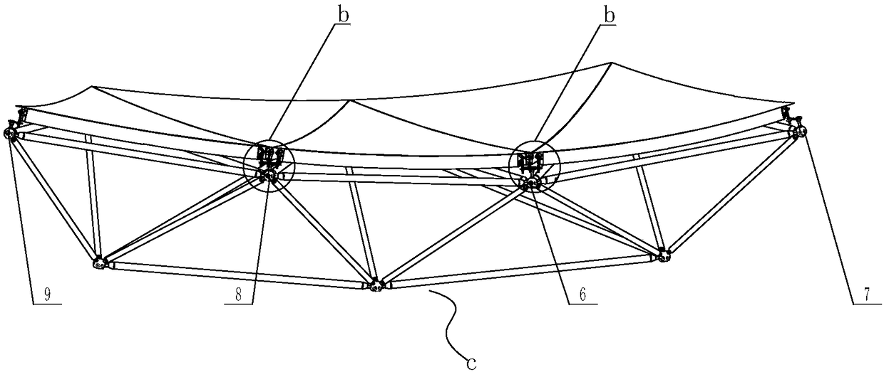
[0041] Embodiment 1, as shown in the figure, the best embodiment of the present invention takes the reflector unit at the edge of the square kilometer array antenna SKA as an example, as figure 1 shown, figure 1It is a schematic diagram of the overall installation structure of the antenna.

[0042] The present invention provides a structure of a high-precision reflector antenna composite panel, including a back frame for supporting a high-precision reflector antenna, and a plurality of panel assemblies 15 are connected to the back frame, and the back frame is composed of a plurality of pull rods Combined to form, the connection points of the tie rods are all supported by bolt balls at all angles. The above-mentioned multiple panel assemblies 15 form a high-precision reflective surface. There are multiple multi-panel panels for adjusting the posture of the panel assembly 15 on the antenna back frame c. Level adjustment unit, each panel assembly 15 and adjacent panel assembly 1...

Embodiment 2

[0044] Embodiment 2 provides a method for adjusting a high-precision reflector antenna combination panel, including the following steps: Please add corresponding numbers to all the corresponding components in the manual, and finally check

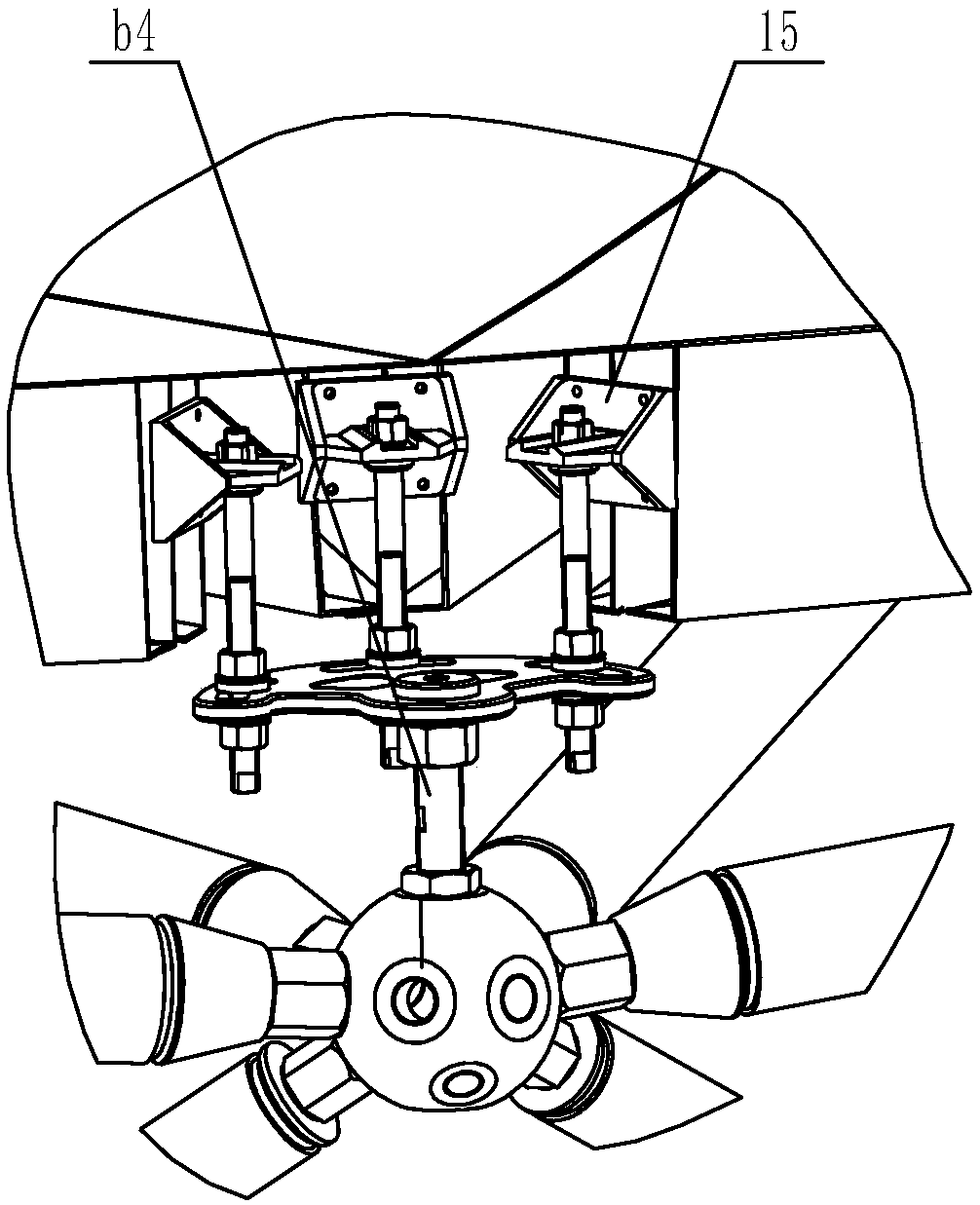
[0045] S1: Design and manufacture displacement adjustment unit b:

[0046] The displacement adjustment unit b includes a coarse displacement adjustment screw b4, a coarse displacement adjustment disc b2, and a fine displacement adjustment screw b3, the coarse adjustment screw b4 is screwed to the back frame, and the coarse displacement adjustment disc b2 is screwed to the coarse On the adjustment screw b4, the displacement coarse adjustment disc b2 is provided with a plurality of slots corresponding to the panel assembly 15 one by one, and each slot is movably connected with a displacement fine adjustment screw b3, and the displacement fine adjustment screw b3 is connected to the panel The components 15 are fixedly connected in one-to-one c...


PUM


Abstract

The invention discloses a structure of a high-precision reflector antenna composite panel and an adjustment method thereof and belongs to the field of high-precision antenna preparation technologies.The structure comprises a main antenna body composed of a high-precision reflector and an antenna back rack, the main antenna body is subjected to relevance-type pre-adjustment through a coarse adjustment disc used for first-level adjustment and subjected to second-level adjustment through a fine adjustment threaded rod used for second-level adjustment after pre-adjustment, and the coarse adjustment disc for first-level adjustment can achieve linkage adjustment on the positions and poses of N panels (expanding to the whole reflector antenna structure, N is equal to 1-6) on the upper portions of panel adjustment points. The whole structure has the advantages of being simple, high in adjustment efficiency, low in weight and processing cost, high in reliability and the like and is particularly suitable for all kinds of reflector antennas with the antenna aperture larger than 18 meters and the working frequency band above the Ka frequency band.

Description

technical field [0001] The invention belongs to the field of high-precision antenna devices, and relates to the structure and adjustment method of a high-precision reflector antenna combination panel in the field of reflector antennas, and is especially suitable for reflectors with large diameters, small curvatures, and operating frequencies above the Ka frequency band Antennas are also used as manufacturing and adjustment technology for high-precision reflector adjustment devices. Background technique [0002] With the great progress of deep space exploration and satellite communication technology, antennas have played a pivotal role in it. The antenna mainly transmits and receives signals through a reflective surface of a specific size. Related technologies require higher and higher operating frequencies of antennas, and furthermore, require higher and higher profile precision of reflector antennas. The adjustment method of the high-efficiency combined panel adjustment d...

Claims


Application Information

Patent Timeline
IPC IPC(8): H01Q15/18
CPCH01Q15/18Y02D30/70
Inventor 刘健泉刘国玺张万才周书中郑元鹏赵均红杜彪李增科张家怡
Owner NO 54 INST OF CHINA ELECTRONICS SCI & TECH GRP
Why Eureka
Try Eureka