A coaxial high-speed direct-drive helicopter and its flight control method
What is Al technical title?
Al technical title is built by PatSnap Al team. It summarizes the technical point description of the patent document.
A helicopter and high-speed technology, applied in the field of aircraft, can solve the problems of complex transmission mechanism, small differential control angle, low reliability and driving efficiency, etc., and achieve the effects of improving system efficiency, reducing system mass, and small moment of inertia
Active Publication Date: 2016-04-27
SUZHOU TAOXUN AVIATION TECH CO LTD
View PDF6 Cites 0 Cited by
Summary
Abstract
Description
Claims
Application Information
AI Technical Summary
This helps you quickly interpret patents by identifying the three key elements:
Problems solved by technology
Method used
Benefits of technology
Problems solved by technology
The pitch of the upper and lower rotors is controlled by the pitch control device, which can realize partial differential control, but the differential control angle is small, and it is impossible to perform single-blade independent pitch change, thus reducing the lift, roll, Maneuverability such as pitching, yaw, and inverted flight cannot achieve all the maneuvering actions of a single-blade helicopter
[0003] Helicopters have excellent characteristics such as vertical take-off and landing, hovering in the air, and inverted flight, but it is difficult to achieve high-speed forward or backward flight, so its application is greatly restricted
[0004] Helicopters in the prior art usually use the engine to drive the reduction gearbox for transmission. This type of helicopter has a heavy structure, complex transmission mechanism, serious friction and wear between gears, high noise, and low reliability and drive efficiency.
Method used
Image
Click on the blue label to locate the original text in one second.
Reading with bidirectional positioning of images and text.
Examples
Embodiment 1
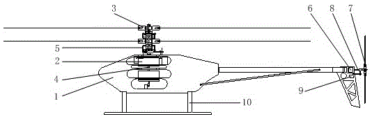
[0030] Such as figure 1Shown is a schematic diagram of the overall structure of a coaxial high-speed direct-drive helicopter disclosed in this embodiment. Disclosed in this embodiment; the coaxial high-speed direct-drive helicopter mainly includes a frame 1, a main rotor engine 2, a main rotor component 3, a main rotor drive shaft 4, a main rotor pitch adjustment component 5, a tail rotor engine 6, and a propulsion tail rotor Part 7, tail rotor drive shaft 8, tail rotor pitch adjustment part 9 and landing gear 10.
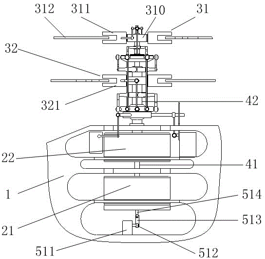
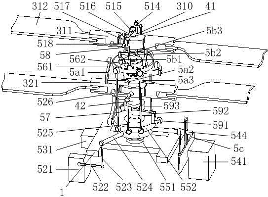
[0031] Such as figure 2 Shown is a schematic diagram of the main rotor drive system and pitch adjustment components of a coaxial high-speed direct-drive helicopter disclosed in this embodiment. Wherein, the main rotor engine 2 is fixedly arranged on the frame 1 . The output shaft of the main rotor engine 2 is fixedly connected with the main rotor transmission shaft 4 to drive the main rotor transmission shaft 4 to rotate, and the main rotor transmission shaft 4...
PUM
Abstract
The invention discloses a coaxial high-speed direct-driven helicopter which comprises a rack, a main rotor engine, a main rotor component, a main rotor drive shaft, a main rotor pitch regulating component, a tail rotor engine, a tail rotor impelling component, a tail rotor drive shaft, a tail rotor steering engine and a landing gear. According to the invention, rotors are directly driven to rotate by using the engines, so that the helicopter has the advantages of high efficiency, low noise, compact structure and reliable system. The main rotor engine is arranged right below the rotors, so that the center of gravity of the helicopter is concentrated, the rotational inertia is small, and the flexibility of maneuvering in the process of flight is improved. The main rotor pitch regulating component is used for regulating a lower rotor pitch, and carrying out linkage regulation on upper and lower rotor pitches, and also can carry out independent regulation on the upper rotor pitch, so that the difference of independent pitches of the upper and lower rotor pitches and the consistency of periodical pitches are realized, thereby improving the maneuvering characteristics such as rise and fall, rolling, pitching, yawing and inverted flight of the helicopter; and in a tail rotor impelling mode, the high-speed forward flight or backward flight of the helicopter can be realized.
Description
technical field [0001] The invention relates to the field of aircraft, in particular to a coaxial high-speed direct-drive helicopter and its flight control method. Background technique [0002] Compared with single-rotor helicopters, coaxial contrarotating-rotor helicopters have shorter rotor spans, lower power consumption, no need to install tail rotors to balance the counter moment generated by rotor rotation, and more flexible structural design. The Kamov Coaxial Reversing Helicopter designed and manufactured by Russia's Kamov Design Bureau is a typical representative of this type of helicopter. The card 50 helicopter uses sleeve-type transmission shafts with different radii as transmission components. The axes of the two transmission shafts coincide and can perform circumferential rotation. The transmission shaft with a larger radius is installed with the lower rotor blades, and the transmission shaft with a smaller radius is installed with Upper rotor blades. The pitc...
Claims
Application Information
Patent Timeline
Application Date:The date an application was filed.
Publication Date:The date a patent or application was officially published.
First Publication Date:The earliest publication date of a patent with the same application number.
Issue Date:Publication date of the patent grant document.
PCT Entry Date:The Entry date of PCT National Phase.
Estimated Expiry Date:The statutory expiry date of a patent right according to the Patent Law, and it is the longest term of protection that the patent right can achieve without the termination of the patent right due to other reasons(Term extension factor has been taken into account ).
Invalid Date:Actual expiry date is based on effective date or publication date of legal transaction data of invalid patent.