
Detection system for single frequency laser mode hopping

A technology for detection systems and lasers, applied in the direction of lasers, optical instrument testing, laser components, etc., can solve other problems such as noise aliasing, long scanning period, and limited scanning spectrum range, and achieve high resolution, simple structure, and high sensitivity high effect

Inactive Publication Date: 2018-06-12
CANALASER TECH
View PDF5 Cites 5 Cited by
  • Summary
  • Abstract
  • Description
  • Claims
  • Application Information

AI Technical Summary

Problems solved by technology

[0004] The detection effect of the intensity noise method is convenient and can be detected in real time, but it is easy to alias with other noises, resulting in misjudgment
[0005] The F-P interferometer scanning method is a commonly used mode-hopping detection method. The mode-hopping detection is realized by directly scanning the F-P cavity, and the frequency shift direction and interval of the mode-hopping can be judged. However, the scanning spectrum range is limited and the scanning period is long. Real-time detection cannot be guaranteed
[0006] The self-delay zero-beat method judges the mode hopping by detecting the beat frequency signal generated during the mode hopping process. When measuring the line width of a single-frequency laser, the frequency shift and mode-hopping characteristics of the single-frequency laser can be judged by detecting the beat frequency signal. , and can accurately detect the frequency shift and interval of mode hopping, the disadvantage is that the test system usually needs to use tens of kilometers of delay fiber, the stability and accuracy of the test results are poor, and the structure of the test system is complex

Method used


Image

  • Detection system for single frequency laser mode hopping
  • Detection system for single frequency laser mode hopping

Examples


Embodiment Construction

[0018] Below in conjunction with specific embodiment, further illustrate the present invention. It should be understood that these examples are only used to illustrate the present invention and are not intended to limit the scope of the present invention. In addition, it should be understood that after reading the teachings of the present invention, those skilled in the art can make various changes or modifications to the present invention, and these equivalent forms also fall within the scope defined by the appended claims of the present application.

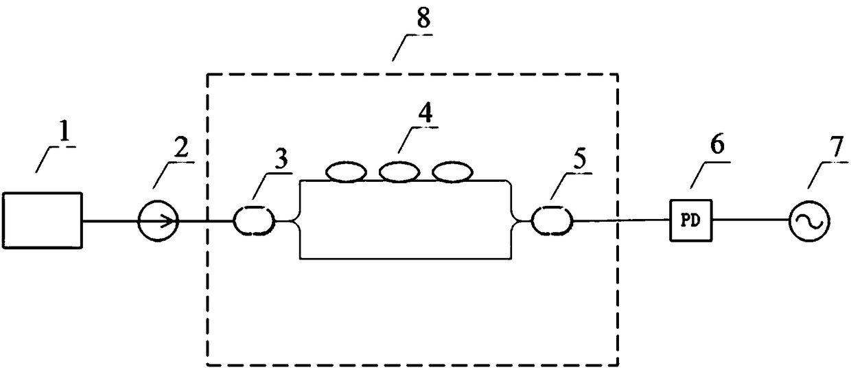
[0019] Embodiments of the present invention relate to a detection system for single-frequency laser mode hopping, including an optical fiber interferometer, a photodetector, and an oscilloscope. The optical fiber interferometer includes a first coupler, a second coupler, a transmission fiber, and a delay fiber , the input end of the first coupler is connected to the single-frequency laser through an optical fiber, and the outpu...


PUM


Abstract

The invention relates to a detection system for single frequency laser mode hopping. The detection system comprises an opto-isolator, a fiber optic interferometer, a photoelectric detector and an oscilloscope, the fiber optic interferometer comprises a first coupler, a second coupler, a transmission fiber and a delay optical fiber, an input end of the first coupler is connected with a single frequency laser through optical fibers, and an output end of the second coupler is connected with the photoelectric detector through optical fiber; the transmission optical fiber and the delay optical fiber are in parallel between the first coupler and the second coupler, so that the output light of the single frequency laser causes interference; the oscilloscope is connected with the photoelectric detector. The detection system for single frequency laser mode hopping can be detected in real time, low in cost and easy to implement.

Description

technical field [0001] The invention relates to the field of single-frequency lasers, in particular to a detection system for mode-hopping of single-frequency lasers. Background technique [0002] Single-frequency lasers have become ideal light sources for various optical detections due to their narrow linewidth and low noise. Single-frequency lasers are widely used in coherent optical communications, lidar, laser remote sensing, laser interception, and high-resolution spectral analysis and other fields. At present, the production technology of single-frequency lasers is becoming more and more mature, but in practical applications, mode-hopping phenomenon still occurs occasionally during long-term operation of single-frequency lasers. Mode-hopping will seriously affect the high coherence of single-frequency light sources and increase the The phase noise, which severely restricts the wide application of single-frequency lasers. Real-time detection of the mode hopping of sin...

Claims


Application Information

Patent Timeline
Patent Type & Authority Applications(China)
IPC IPC(8): H01S3/00H01S5/00G01M11/00
CPCG01M11/00H01S3/0014H01S5/0014
Inventor 曹建建王飞利马晓伟楼慈波
Owner CANALASER TECH
Learn More