Aerosol propellant grain ignition device and production method

An aerosol generation and generation agent technology, which is applied in fire rescue and other fields, can solve the problems of deflagration, explosion, structural stability and protection of powder columns, etc.

Active Publication Date: 2018-06-15
YICHANG JI AN DUN FIRE FIGHTING TECH CO LTD
View PDF5 Cites 1 Cited by
  • Summary
  • Abstract
  • Description
  • Claims
  • Application Information

AI Technical Summary

Problems solved by technology

However, if there are cracks in the pyrotechnic powder column during production or transportation, it may cause deflagration of the powder column, and the sudden rise of UHV gas is too late to release. Once the pressure exceeds the pressure limit of the device itself, an explosion will occur, thereby triggering Serious damage to the operator and the surrounding machinery and equipment; in addition, the operating environment of the device may have various harsh conditions such as high-frequency vibration, high humidity, and high salt spray corrosion. If the structural stability and protection of the device itself cannot meet the requirements, May cause device failure
[0003] However, most of the current aerosol fire extinguishing devices do not have corresponding measures or means to solve the above problems. Therefore, the structure of the existing aerosol fire extinguishing devices must be improved in order to effectively avoid personnel injuries caused by deflagration and device failure during use.

Method used


Image

  • Aerosol propellant grain ignition device and production method
  • Aerosol propellant grain ignition device and production method
  • Aerosol propellant grain ignition device and production method

Examples


Embodiment 1

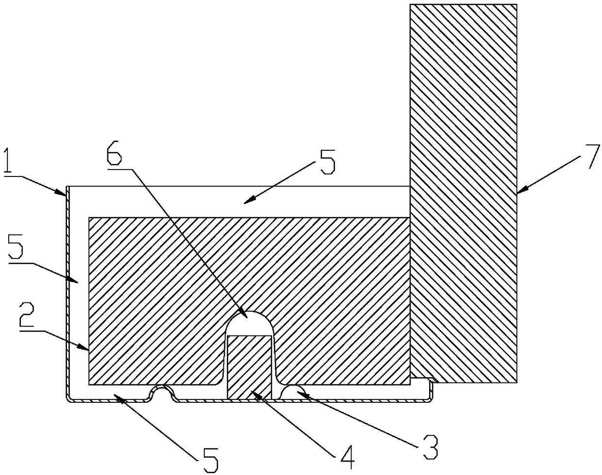
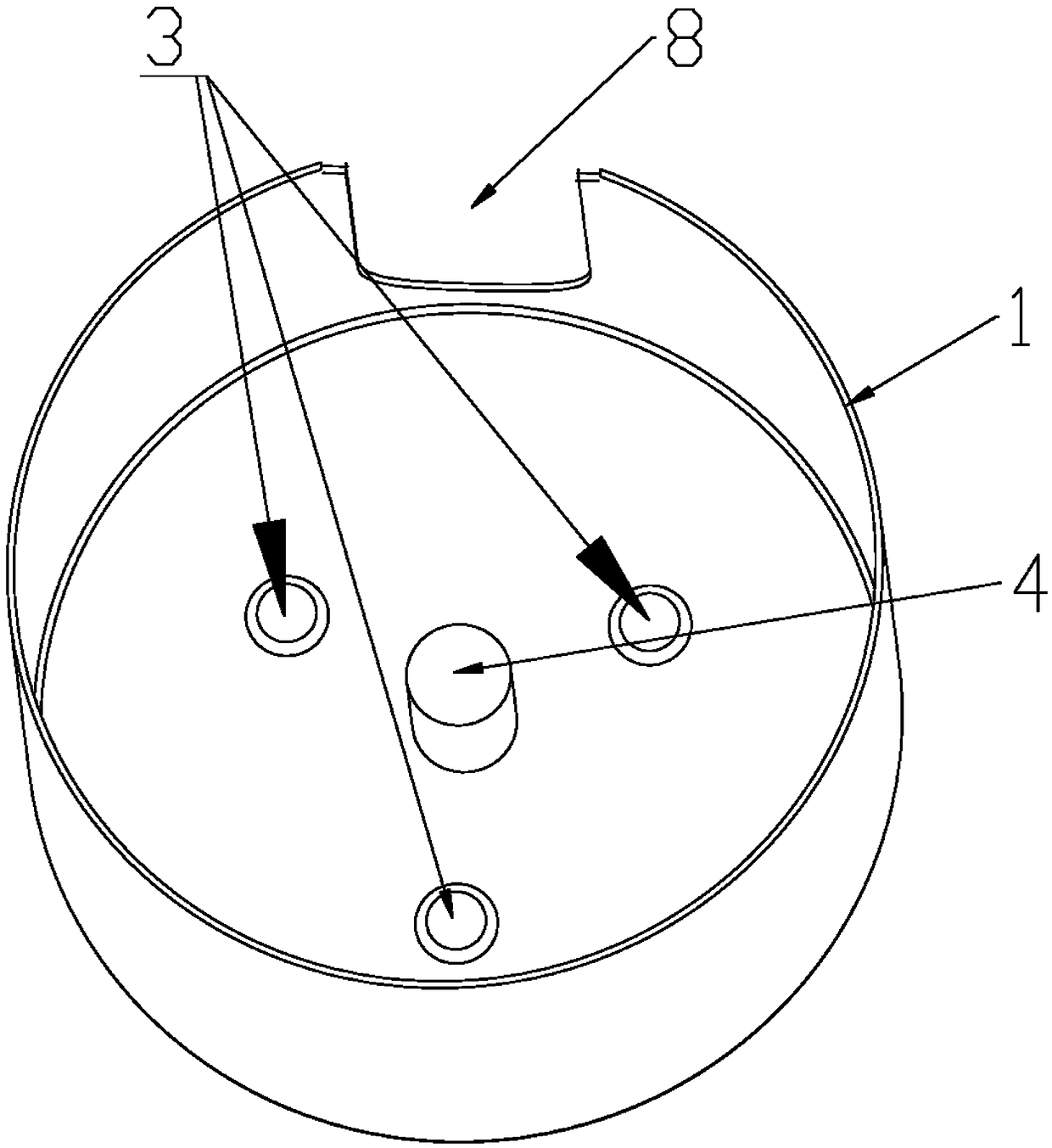
[0031] see Figure 1-4 , a kind of aerosol generating agent charge ignition device, it comprises generating agent cylinder 1, and described generating agent cylinder 1 is fixed and reaction container, and the side wall of described generating agent cylinder 1 is provided with opening 8; Said opening The dispensing jig 7 is positioned and installed on 8, and the bottom of the generator cartridge 1 is positioned and installed with a drug column 2 through the axial positioning structure 3 and the radial positioning structure 4.

[0032] Further, the gap between the generator cartridge 1 and the grain column 2 is filled with a silica gel isolation layer 5 and covers the entire grain column 2 .

[0033] Further, the dispensing jig 7 is in close contact with the side of the grain column 2 .

[0034] Further, the number of the dispensing jig 7 is at least one, and the number is determined according to the number of openings 8 on the side wall of the generator cartridge 1 .

[0035]...

Embodiment 2

[0041] The method for any aerosol generating agent grain ignition device, it comprises the following steps:

[0042] Step1: Put the formed aerosol generating agent grain 2 into the aerosol generating agent cartridge 1 with the axial positioning structure 3 and the radial positioning structure 4;

[0043] Step 2: Put the dispensing jig 7 into the opening 8 of the side wall of the aerosol generating agent cartridge 1 and ensure that the side of the dispensing jig 7 is in close contact with the side of the aerosol generating agent column 2;

[0044] Step 3: Inject a certain amount of liquid silica gel into the aerosol generating agent cylinder 1, and after the silica gel is allowed to stand and solidify, the relative positions of the powder column 2 and the generating agent cylinder 1 are fixed as a whole, and a stable silica gel isolation layer is formed between the two 5;

[0045] Step 4: Remove the glue dispensing jig 7 to expose the burning surface of the aerosol generating ...


PUM


Abstract

The invention provides an aerosol propellant grain ignition device and a production method. The ignition device comprises a propellant cylinder, and the propellant cylinder is a container for fixationand reaction; an opening is formed in the side wall of the propellant cylinder; a dispensing jig is arranged on the opening in a positioned mode; and a grain is arranged at the bottom of the propellant cylinder through axial positioning structures and a radial positioning structure in a positioned mode. The aerosol propellant grain ignition device and the production method aim to overcome the technological defects of an existing aerosol fire extinguishing device propellant grain in the production process and have the advantages that the aerosol propellant grain can be effectively ignited, meanwhile, the combustion of the aerosol propellant grain can be effectively improved, and the overall structural stability can be ensured.

Description

technical field [0001] The invention relates to a gas fire extinguishing technology in the field of fire safety, in particular to a production method capable of effectively igniting an aerosol generating agent powder column while effectively improving the combustion and overall structural stability of the aerosol generating agent powder column. Background technique [0002] At present, the existing fire extinguishers use the pyrotechnic agent with a faster burning rate as the main agent, which is made into a powder column by molding and fixed in the generator cartridge. When the product works normally, the powder column burns in an orderly and stratified manner to produce a stable aerosol smoke. However, if there are cracks in the pyrotechnic powder column during production or transportation, it may cause deflagration of the powder column, and the sudden rise of UHV gas is too late to release. Once the pressure exceeds the pressure limit of the device itself, an explosion wi...

Claims


Application Information

Patent Timeline
Patent Type & Authority Applications(China)
IPC IPC(8): A62C5/033A62C5/00
CPCA62C5/00A62C5/033
Inventor 雷耀华李先军张俊峰
Owner YICHANG JI AN DUN FIRE FIGHTING TECH CO LTD
Why Eureka
Try Eureka