Tightness-adjustable automatic operation device

An operating equipment and elastic technology, which is applied in the field of automatic operating equipment, can solve the problems of restricting the application field of grasping and climbing auxiliary devices, the danger of staff working at heights, and single-targetedness, so as to improve operating efficiency, reduce labor intensity, and improve grasping and climbing. speed effect

Active Publication Date: 2018-06-15
宁波顺凯新材料科技有限公司
View PDF5 Cites 8 Cited by
  • Summary
  • Abstract
  • Description
  • Claims
  • Application Information

AI Technical Summary

Problems solved by technology

[0002] For a long time, in the field of automatic vertical crawling technology, there are few related automatic machines that are capable of this task, especially in the on-site work of power supply line maintenance, the staff often need to use their feet to climb onto the utility poles to carry out related power equipment. For inspection and maintenance, at present, foot buckles are mainly used for climbing electric poles. The design of the foot buckles can easily lead to such a situation. Accidentally step on the air with one foot, causing the center of gravity to become unstable, causing the body to move sideways, and the other foot buckle to leave the pole , less secure
In addition, the diameter of the utility pole gradually decreases with the increase of height, and the foot buckle is easy to fall off when the staff pushes the pole too fast
Moreover, due to the use of new steel structure utility poles in some areas of the city, the foot buckle cannot adapt to the change of the diameter of the utility pole, thereby bringing the danger of working at heights to the staff. At the same time, the existing crawling auxiliary device The pertinence is relatively single, and it can only be applied to target crawlers with specific shapes and structures, thus limiting the application field of crawling aids

Method used


Image

  • Tightness-adjustable automatic operation device
  • Tightness-adjustable automatic operation device
  • Tightness-adjustable automatic operation device

Examples


Embodiment Construction

[0035] The present invention will be further described in detail below in conjunction with the accompanying drawings, so that those skilled in the art can implement it with reference to the explanatory text.

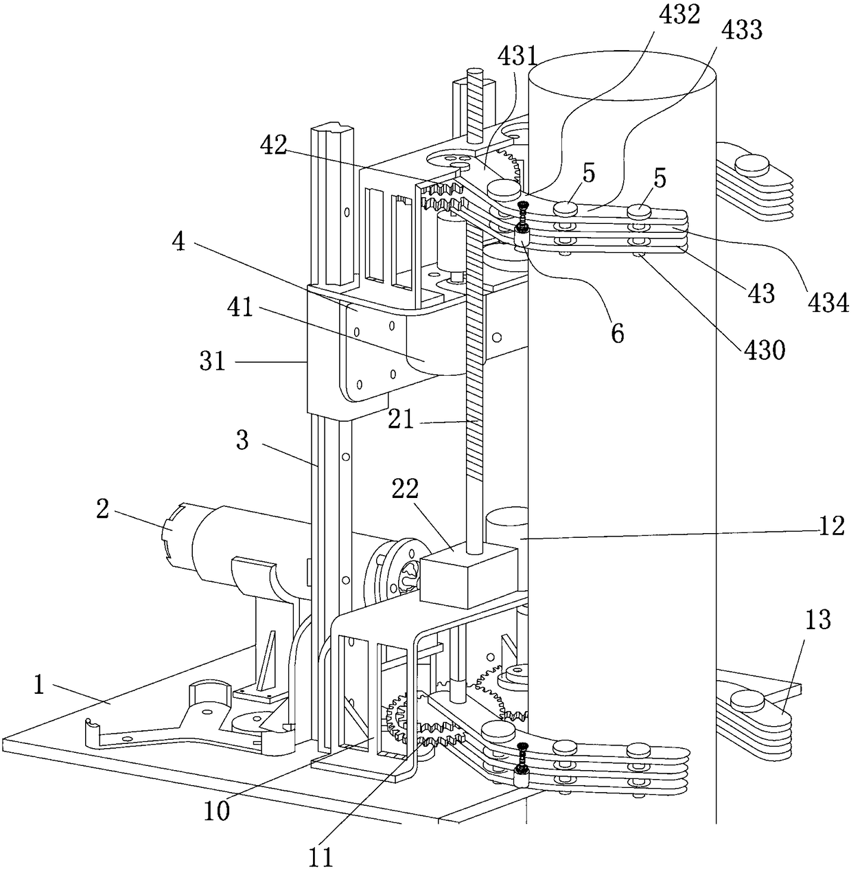
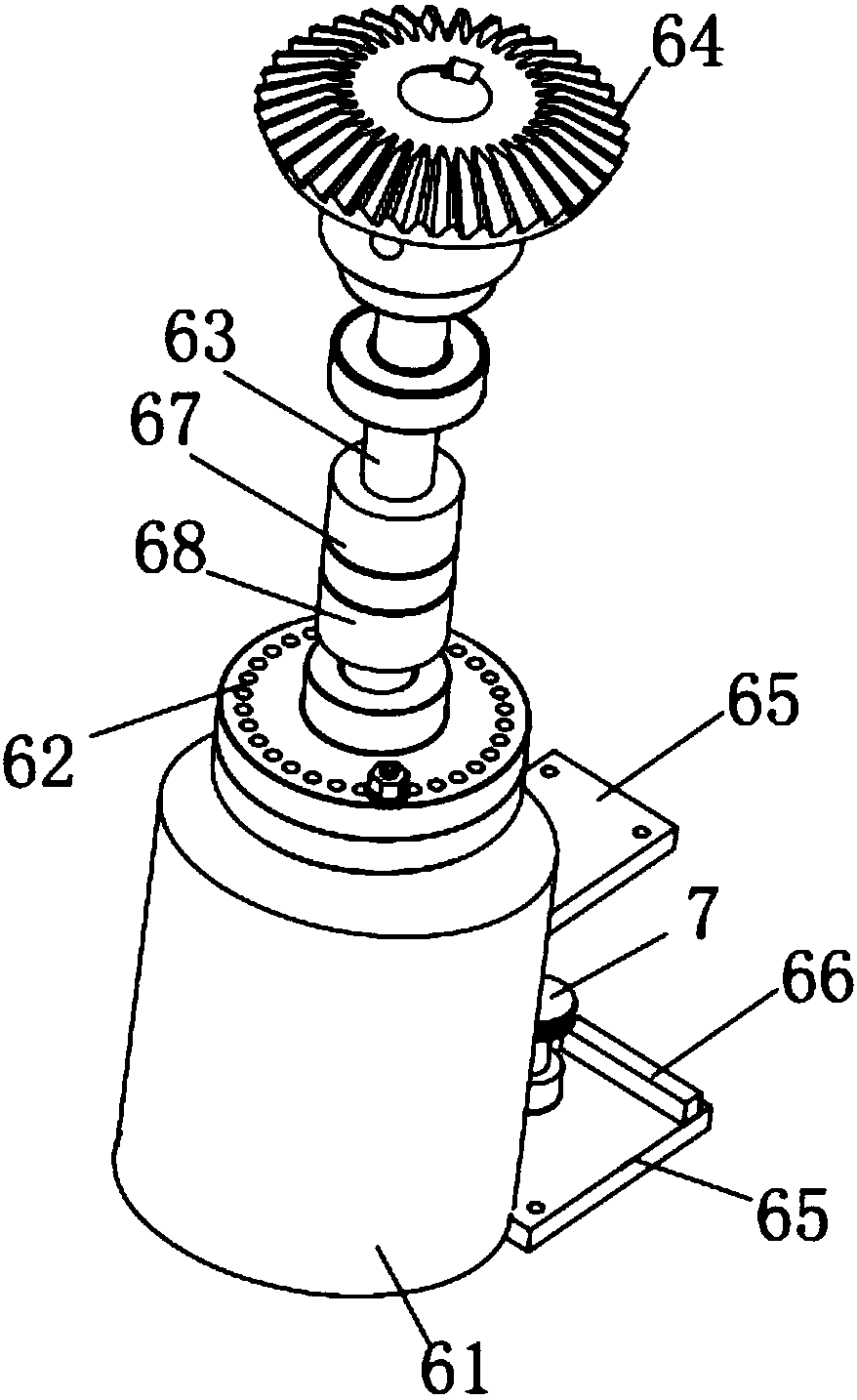
[0036] Such as Figure 1-6 As shown, the present invention provides an automatic operation device with adjustable elasticity, which includes a display module, an infrared distance measuring module, a manipulator, a rotating and telescopic module, and a driving mechanism.

[0037] Specifically, the LCD display module is arranged on the top of the operating equipment to realize the real-time display of the status of the upper and lower manipulators and the current position of the operating equipment. The LCD display module is connected with the controller of the operating equipment. Buttons are used to control the controller, and finally the buttons control the start and stop of the running equipment, the grasping and releasing of the manipulator, the rotation process of e...


PUM


Abstract

The invention discloses a tightness-adjustable automatic operation device. For the tightness-adjustable automatic operation device, linear displacement spherosyns are arranged in guide rails, readingheads are arranged in sliding sleeves, the tightness-adjustable automatic operation device further comprises at least two manipulators and a main motor, the main motor is fixedly mounted on a bottom plate of the operation device, an output shaft of the main motor is in linkage with the sliding sleeves through a reduction gearbox and a lead screw, each manipulator is composed of a pair of mechanical arms capable of rotating in an opposite way, each mechanical arm is composed of a plurality of sections of movable joints, the movable joints are rotatably connected through rotation shafts, at least two grooves are axially symmetrically formed in each rotation shaft, a guide rod is telescopically arranged in each groove, a first contrate gear is horizontally arranged at the upper end of each guide rod, a first drive mechanism is slidingly arranged at the upper end of each mechanism arm, a second contrate gear is telescopically arranged at the upper end of each first drive mechanism, and each second contrate gear is in selective linkage with the corresponding first contrate gear. With the tightness-adjustable automatic operation device, the technical problem that the mechanical arms on the existing grabbing and climbing devices are fixed in form, consequently, the application range is limited, is solved.

Description

technical field [0001] The invention relates to the technical field of automatic control, in particular to an automatic operation device with adjustable tension. Background technique [0002] For a long time, in the field of automatic vertical crawling technology, there are few related automatic machines that are capable of this task, especially in the on-site work of power supply line maintenance, the staff often need to use their feet to climb onto the utility poles to carry out related power equipment. For inspection and maintenance, at present, foot buckles are mainly used for climbing electric poles. The design of the foot buckles can easily lead to such a situation. Accidentally step on the air with one foot, causing the center of gravity to become unstable, causing the body to move sideways, and the other foot buckle to leave the pole , less secure. In addition, the diameter of the utility pole gradually decreases as the height increases, and the foot buckle is easy ...

Claims


Application Information

Patent Timeline
Patent Type & Authority Applications(China)
IPC IPC(8): A63B27/04B25J9/10B25J15/00B62D57/024
CPCA63B27/04B25J9/109B25J15/0052B62D57/024
Inventor 储建华高霞
Owner 宁波顺凯新材料科技有限公司
Why Eureka
Try Eureka