Energy-saving direct current charging pile and charging method

A technology of DC charging and charging piles, which is applied in charging stations, efficient vehicle charging, and modification of power electronics. The effect of reducing module life and standby loss

Active Publication Date: 2018-06-15
长园深瑞继保自动化有限公司 +1
View PDF8 Cites 5 Cited by
  • Summary
  • Abstract
  • Description
  • Claims
  • Application Information

AI Technical Summary

Problems solved by technology

[0002] As the core component of the DC charging pile, the charging module has a standby loss of not less than 1‰. For example, a 120kW charging pile has a standby loss of 2.88kW*h a day, and a charging station has 100 charging piles, and its loss is as high as 288kW*h. For operators is a huge loss
The characteristic of the charging module is that when it runs at the rated current, its efficiency is the highest, the power factor is the highest, and the harmonics are the smallest. At present, when the charging pile is charging the electric vehicle, it is difficult to satisfy the charging module running at the rated current, which will inevitably cause a certain amount of waste of electric energy.
The fan is another power device of the charging pile. Its main function is to dissipate heat. Generally, the power of the fan is large and there is a certain operating loss. At present, the fan is started when the charging pile is charging in the industry, but when the charging load is small, the charging pile The internal temperature is not high, there is no need to start the fan

Method used


Image

  • Energy-saving direct current charging pile and charging method
  • Energy-saving direct current charging pile and charging method

Examples


Embodiment Construction

[0041] Below in conjunction with embodiment the present invention is further described.

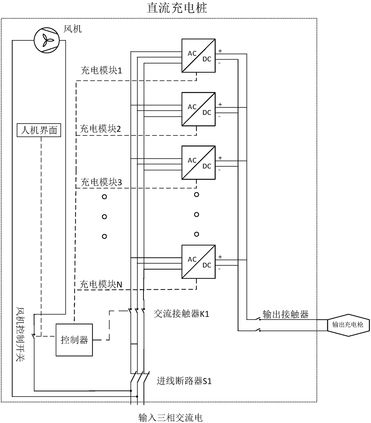
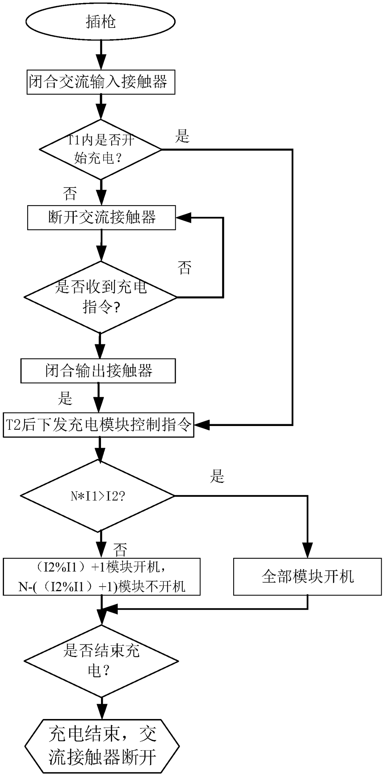
[0042] Such as figure 1 , figure 2 As shown, an energy-saving DC charging method includes the following steps before charging:

[0043] 1A. The AC contactor K1 is disconnected before charging to reduce the standby loss of the charging module; the main circuit of the DC charging pile needs to be installed with an AC contactor to control the AC main circuit of the charging module.

[0044] 1B. Insert the DC charging gun into the charging port of the electric vehicle, and close the AC contactor K1.

[0045] 1C. The man-machine interface prompts that the charging cable is connected and starts timing.

[0046] 1D. If the charging command is received within time t1, the AC contactor K1 remains closed, and the charging pile controller issues a charging command to the charging module to enter step 1E; if the charging command has not been received after time t1, the AC contactor K1 The contac...


PUM


Abstract

The invention discloses an energy-saving direct current charging method comprising the following steps that (1), a direct current charging pile is configured with an alternating current contactor; (2), the alternating current contactor is disconnected before starting charging, and the standby power loss of a charger module is reduced; (3), the alternating current contactor is closed when chargingis started, the charger module is put into use according to current demand, the operating efficiency of the charger module is improved, and the electric quantity is saved; (4), the alternating currentcontactor is disconnected after the charging is finished, and the standby power loss of the charger module is reduced; and (5), a power draught fan is controlled to start and stop according to the temperature in a charging pile cabinet, and the power draught fan running power waste is avoided. The energy-saving direct current charging method can reduce standby and running loss of the direct current charging pile in the industry before charging, during charging and after charging, and the operation efficiency is improved.

Description

technical field [0001] The invention relates to the field of electric vehicle charging, in particular to an energy-saving charging pile and a charging method. Background technique [0002] As the core component of the DC charging pile, the charging module has a standby loss of not less than 1‰. For example, a 120kW charging pile has a standby loss of 2.88kW*h a day, and a charging station has 100 charging piles, and its loss is as high as 288kW*h. For operators is a huge loss. The characteristic of the charging module is that when it runs at the rated current, it has the highest efficiency, the highest power factor, and the smallest harmonics. At present, when charging electric vehicles, it is difficult for the charging pile to satisfy the charging module running at the rated current, which will inevitably cause a certain amount of waste of electric energy. The fan is another power device of the charging pile. Its main function is to dissipate heat. Generally, the power of ...

Claims


Application Information

Patent Timeline
Patent Type & Authority Applications(China)
IPC IPC(8): B60L11/18H05K7/20
CPCB60L53/20B60L53/31B60L58/12H05K7/20909Y02T10/70Y02T10/7072Y02T10/92Y02T90/12Y02T90/14
Inventor 陈锐许青松祖连兴王汝泉刘冰
Owner 长园深瑞继保自动化有限公司
Why Eureka
Try Eureka