Goods fork equipment and use method thereof

A technology of forks and equipment, which is applied in the field of production line logistics and conveying systems, can solve problems such as product cycle delays, process task accumulation, and cabinets cannot be assembled in parallel, so as to improve the production capacity of assembly stations, meet flexible and changeable requirements, and meet market demand Effect

Pending Publication Date: 2018-06-15
NINGXIA LICHENG ELECTRIC GROUP
View PDF0 Cites 0 Cited by
  • Summary
  • Abstract
  • Description
  • Claims
  • Application Information

AI Technical Summary

Problems solved by technology

[0003] 1. The cabinet body cannot be assembled continuously. After the cabinet body is assembled on the workbench, the posture must be changed before it can be transferred to the next process. During the process, the cabinet body cannot be assembled immediately, and the operator needs to withdraw from the work area when the posture is changed. Only then can the safe posture conversion of the cabinet body be carried out. At this time, the assembly operator needs to wait for the operation table to complete all the actions, and then wait for the operation table to reset before proceeding to the assembly operation, which obviously affects the efficiency of the cabinet assembly operation.
[0004] 2. The cabinets cannot be assembled in parallel. The existing cabinet assembly workbench and posture conversion device are serial interfaces, so that the entire production line can only accommodate two assembly workbenches, and it is impossible to carry out multi-process parallel production methods. When faced with multiple The production tasks with multiple batches of orders lead to a tense production rhythm in the assembly process, which is prone to accumulation of process tasks, resulting in delays in the product cycle
As a result, the production capacity of the production line cannot be well adapted to the flexible and changeable market demand

Method used


Image

  • Goods fork equipment and use method thereof
  • Goods fork equipment and use method thereof
  • Goods fork equipment and use method thereof

Examples


Embodiment Construction

[0029] The following will clearly and completely describe the technical solutions in the embodiments of the present invention with reference to the accompanying drawings in the embodiments of the present invention. Obviously, the described embodiments are only some, not all, embodiments of the present invention. Based on the embodiments of the present invention, all other embodiments obtained by persons of ordinary skill in the art without making creative efforts belong to the protection scope of the present invention.

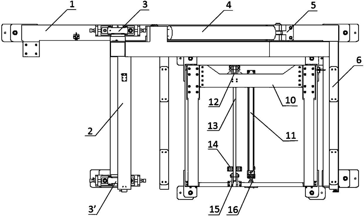
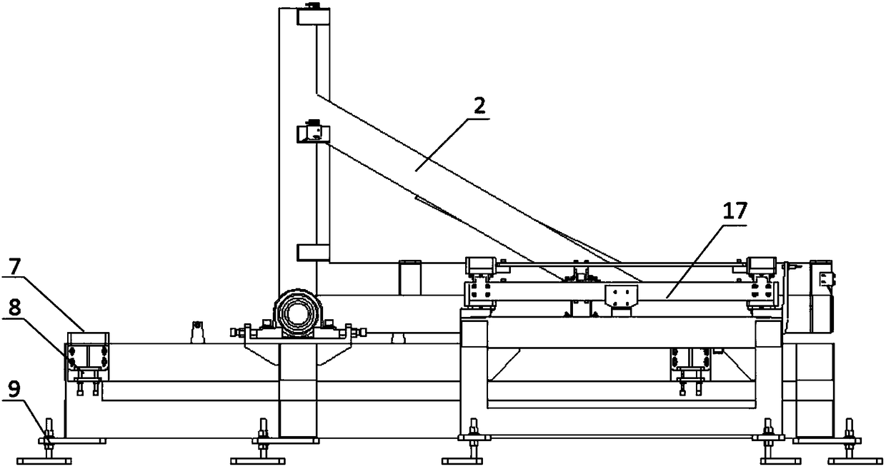
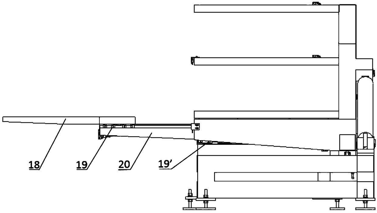
[0030] The purpose of the present invention is to provide a kind of fork equipment and its use method, which has solved the problems of the above-mentioned prior art, can make the cabinet assembly process in the switchgear production line can be operated continuously, reduce the equipment preparation work before the assembly operation, and at the same time Operators do not need to evacuate the work area and wait for the cabinet posture changeover process, which...


PUM


Abstract

The invention discloses goods fork equipment which comprises a rack, roll-over stands, a hydraulic cylinder and a telescopic goods fork; one ends of the roll-over stands are rotationally connected with and fixed to the rack; the hydraulic cylinder is fixedly arranged on the rack and is used for pushing the roll-over stands to carry out angle rotation; the goods fork is subjected to sliding fixingthrough sliding blocks in straight guide rails fixedly arranged on the rack; and the goods fork is arranged at the top of the roll-over stands. According to the goods fork equipment and the use methodof the goods fork equipment, a cabinet body assembling process in a switch equipment production line can operate continuously, equipment preparation work before assembly work is reduced, an operatordoes not need to evacuate from an operating zone or wait in cabinet body gesture conversion and order changing processes, the labor intensity of the operator is reduced, and the safety of the operating process is improved; and the assembling processes of the switch equipment production line can be configured in accordance with productive capacity and market demands flexibly, and the production efficiency is improved.

Description

technical field [0001] The invention relates to the technical field of production line logistics conveying systems, in particular to a pallet fork device and a usage method thereof. Background technique [0002] The logistics conveying system of the production line is mainly responsible for the movement of the spatial position of the material, and the efficient logistics conveying system can ensure the fast and accurate conveying of the material. The performance of the conveying equipment directly determines the rational layout and operating efficiency of the logistics conveying system. Especially when it comes to the logistics conveying system of the switchgear production line, due to the characteristics of the product, the materials it conveys are sheet metal cabinets with large dimensions and weight. In the current production line cabinet transfer process, there are mainly the following problems: [0003] 1. The cabinet body cannot be assembled continuously. After the ca...

Claims


Application Information

Patent Timeline
IPC IPC(8): B66F9/12B66F9/22
CPCB66F9/12B66F9/22
Inventor 牛广军马磊徐志姚利飞谢宁刘海龙王凤旗
Owner NINGXIA LICHENG ELECTRIC GROUP
Why Eureka
Try Eureka