Cabinet door structure and mirror cabinet
A cabinet door and cabinet body technology, applied in windows/doors, building components, door/window accessories, etc., can solve the problems of unstable operation process, complicated assembly process, large space occupation, etc., and achieve simple structure and large compression stroke , the effect of stable operation
- Summary
- Abstract
- Description
- Claims
- Application Information
AI Technical Summary
Problems solved by technology
Method used
Image
Examples
Embodiment 1
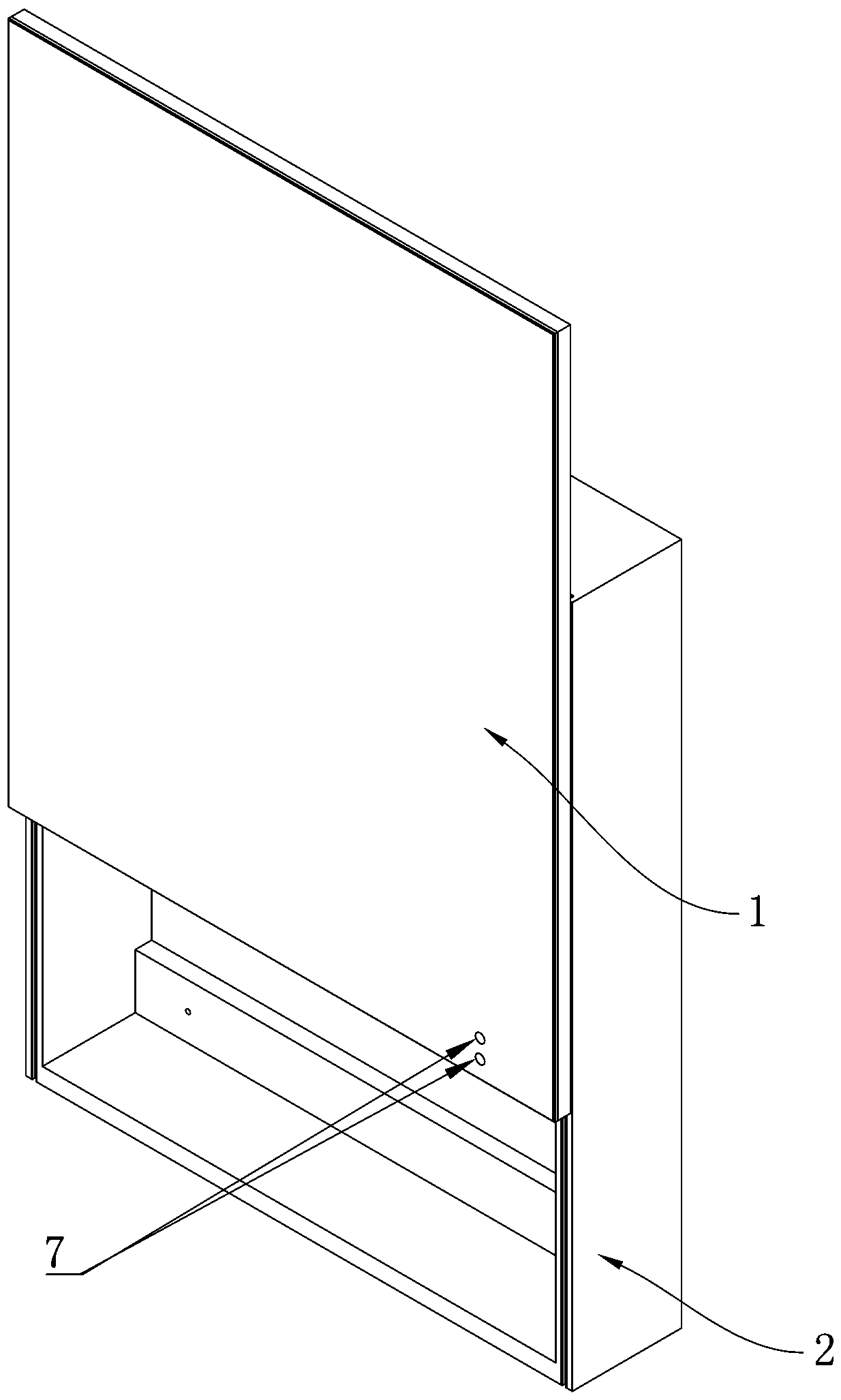
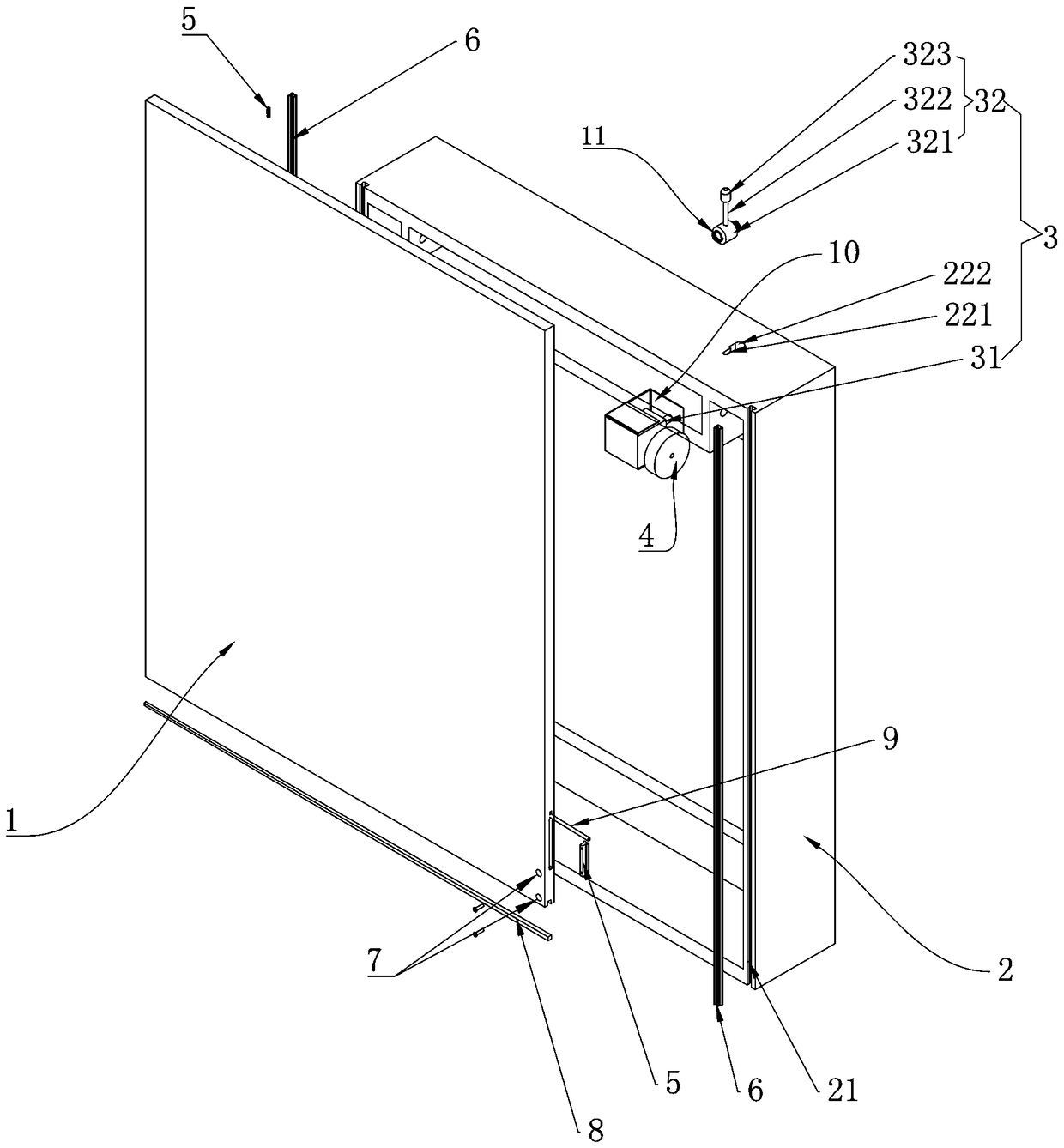
[0054] Such as figure 2 As shown, the fixed seat 10 is set, the fixed seat 10 is installed in the cabinet body 2, the drive unit 3 is installed in the fixed seat 10, the setting of the fixed seat 10, the operation of the motor 31 is more stable when it is working, and it is not easy to deviate, so that The friction wheel 4 connected to the output end of the motor 31 is more stable when abutting against the dodge door 1 .
[0055] The drive unit 3 also includes an adjustment member 32, which is fixedly connected to one side of the motor 31; it also includes an elastic member 11, which is arranged between the motor 31 and the inner surface of the fixed seat 10 or the inner surface of the adjustable member 32 and the fixed seat 10 Between, in this embodiment, the elastic member 11 is a spring, and the elastic member 11 is arranged between the adjustment member 32 and the inner surface of the fixed seat 10, so that the elastic member 11 pushes against the adjustment member 32 to ...
Embodiment 2
[0059] Such as Figure 4 , Figure 5 , Figure 6 and Figure 7 As shown, the fixed seat 10 is set, the fixed seat 10 is installed in the cabinet body 2, the drive unit 3 is installed in the fixed seat 10, the setting of the fixed seat 10, the operation of the motor 31 is more stable when it is working, and it is not easy to deviate, so that The friction wheel 4 connected to the output end of the motor 31 is more stable when abutting against the dodge door 1 .
[0060]A clutch mechanism 12 is provided, and the output end of the motor 31 is connected with the friction wheel 4 through the clutch mechanism 12 . Under normal circumstances, the output end of motor 31 is connected with friction wheel 4 by clutch mechanism 12, and motor 31 drives friction wheel 4 to drive dodge door 1 motion; Friction wheel 4 separates, and like this, motor 31 can not drive friction wheel 4 to rotate, and the frictional force between friction wheel 4 and dodge door 1 reduces, is convenient to manu...
Embodiment 3
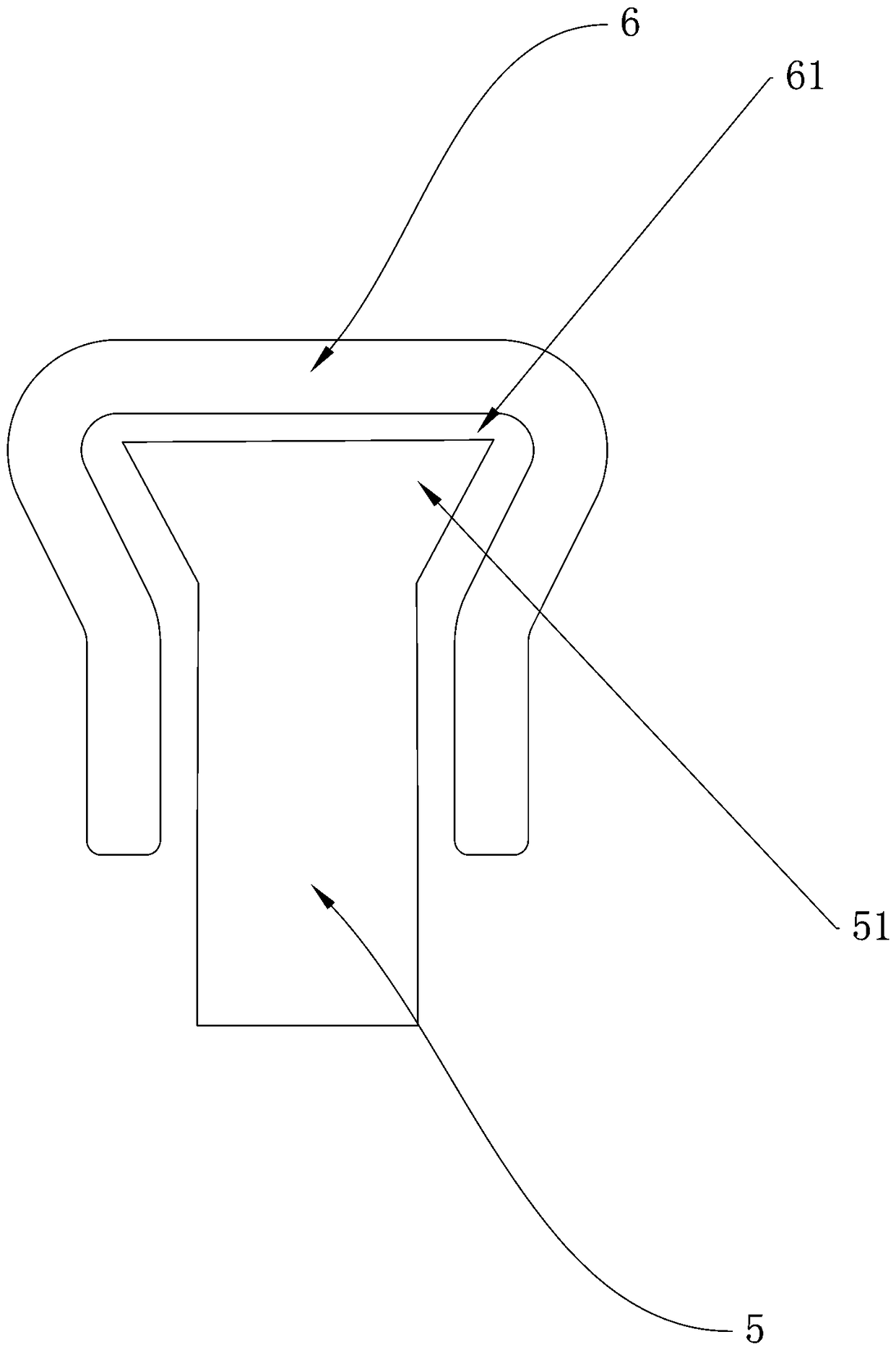
[0067] When the dodge door 1 moves up and down, the motor 31 self-locks the motor 31, and the frictional force between the slide block 5 and the slide rail 6 is greater than or equal to the gravity of the dodge door 1.
[0068] When motor 31 breaks down or situations such as power failure, because motor 31 is a self-locking motor 31, then stop rotating in the situation of breaking down or power failure, because the frictional force between slide block 5 and slide rail 6 is greater than or equal to that of dodge door 1 Gravity, when the dodge door 1 is opened, the friction between the slide block 5 and the slide rail 6 can prevent the dodge door 1 from falling, and the user can still use it.
[0069] The present invention simultaneously provides a kind of mirror cabinet, comprises above-mentioned dodge door 1 structure, also comprises mirror (not shown in the figure), and mirror is installed on dodge door 1, and the mirror cabinet of the present invention has simple drive struct...
PUM
 Abstract
Description
Claims
Application Information
 - R&D
- Intellectual Property
- Life Sciences
- Materials
- Tech Scout
- Unparalleled Data Quality
- Higher Quality Content
- 60% Fewer Hallucinations
Browse by: Latest US Patents, China's latest patents, Technical Efficacy Thesaurus, Application Domain, Technology Topic, Popular Technical Reports.
© 2025 PatSnap. All rights reserved.Legal|Privacy policy|Modern Slavery Act Transparency Statement|Sitemap|About US| Contact US: help@patsnap.com


