
Control system of rotary jetting drilling rig and rotary jetting drilling rig

A technology of control system and drilling rig, which is applied to the automatic control system of drilling, drilling with liquid/gas jet, earthwork drilling and production, etc. It can solve the problem of no alarm device, etc., and achieve the effect of reducing labor intensity and improving automatic control

Pending Publication Date: 2018-06-15
JIANGSU XCMG CONSTR MASCH RES INST LTD
View PDF12 Cites 1 Cited by
  • Summary
  • Abstract
  • Description
  • Claims
  • Application Information

AI Technical Summary

Problems solved by technology

The decompression of high-pressure fluid in the prior art is completely dependent on manual adjustment, and there is no alarm device

Method used


Image

  • Control system of rotary jetting drilling rig and rotary jetting drilling rig
  • Control system of rotary jetting drilling rig and rotary jetting drilling rig
  • Control system of rotary jetting drilling rig and rotary jetting drilling rig

Examples


Embodiment Construction

[0027] The following will clearly and completely describe the technical solutions in the embodiments of the present invention with reference to the accompanying drawings in the embodiments of the present invention. Obviously, the described embodiments are only some, not all, embodiments of the present invention. The following description of at least one exemplary embodiment is merely illustrative in nature and in no way taken as limiting the invention, its application or uses. Based on the embodiments of the present invention, all other embodiments obtained by persons of ordinary skill in the art without creative efforts fall within the protection scope of the present invention.

[0028] The relative arrangements of components and steps, numerical expressions and numerical values ​​set forth in these embodiments do not limit the scope of the present invention unless specifically stated otherwise. At the same time, it should be understood that, for the convenience of descriptio...


PUM


Abstract

The invention discloses a control system of a rotary jetting drilling rig and the rotary jetting drilling rig. The control system of the rotary jetting drilling rig comprises a control valve, a pilothandle and a controller, wherein the control valve and the pilot handle are used for controlling the speed of a power head, and the controller is arranged to be coupled with a control valve. In a drilling state, the pilot handle controls the speed of the power head; and in a rotary jetting lifting state, the controller automatically controls the control valve to do movements according to the speedset value so as to control the speed of the power head. The control system of the rotary jetting drilling rig achieves automatic control over the speed of the power head, so that the control accuracyof the speed of the power head is improved, and the labor intensity of workers is reduced.

Description

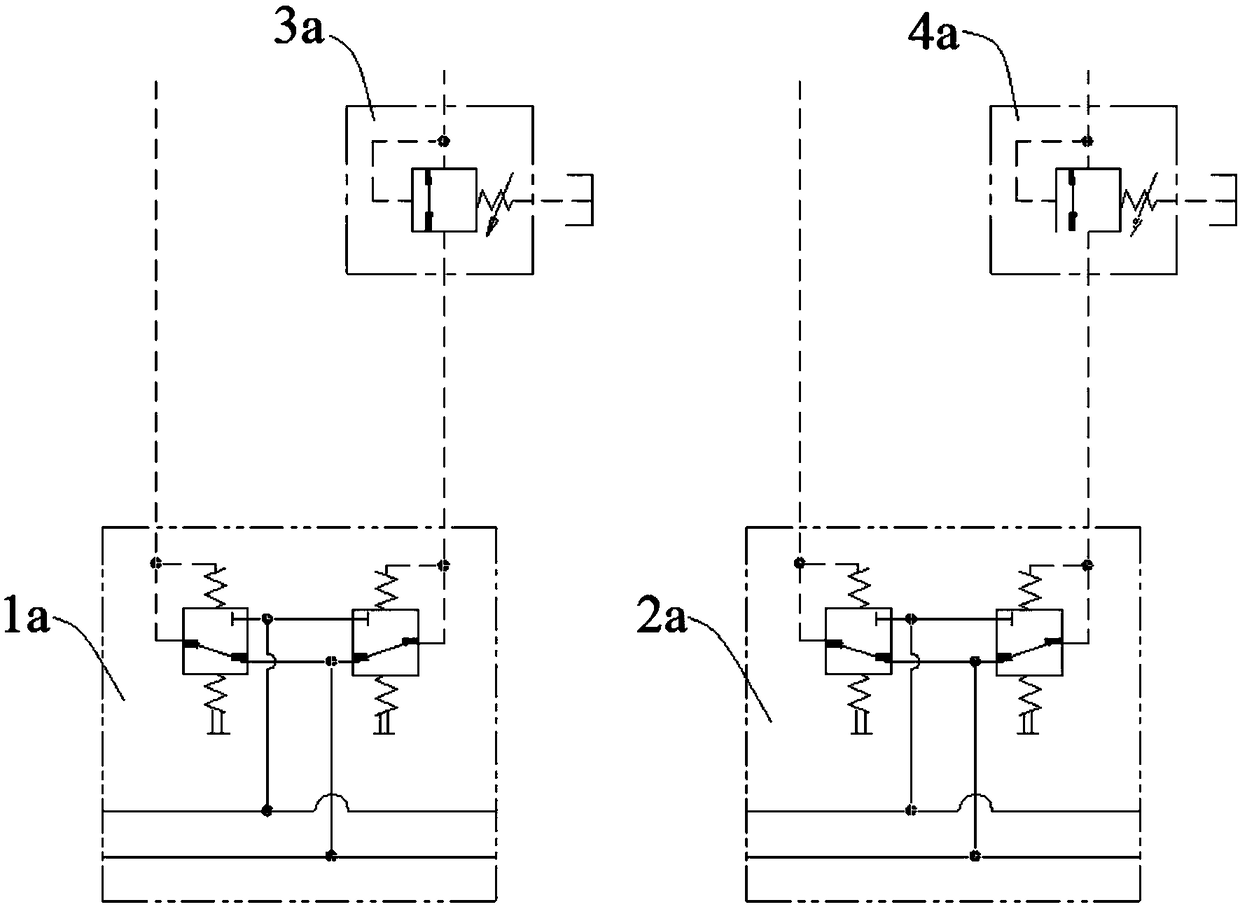
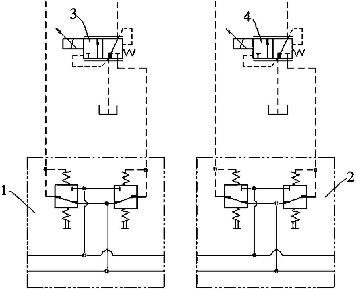
technical field [0001] The invention relates to the technical field of engineering machinery, in particular to a control system of a jet-jet drilling machine and the jet-jet drilling machine. Background technique [0002] The high-pressure rotary spraying construction includes two working conditions of drilling and rotary spraying lifting. In the drilling condition, the speed of the power head does not need to be adjusted and the feed speed does not need to be adjusted accurately; The rotational speed and the speed of the rotary jet lifting need to be adjusted precisely. Such as figure 1 As shown, the control system of the rotary jet drilling machine in the prior art includes a first pilot handle 1a for controlling the lifting speed of the power head, a first manual pressure relief valve 3a and a second pilot handle 2a for controlling the speed of the power head And the second manual decompression valve 4a, because the adjustment of the rotating speed of the power head and...

Claims


Application Information

Patent Timeline
IPC IPC(8): E21B44/00E21B7/18E21B21/08
CPCE21B7/18E21B21/08E21B44/00
Inventor 李明帅吕晓晓侯杭州
Owner JIANGSU XCMG CONSTR MASCH RES INST LTD
Learn More