
Rotary vane engagement variable capacity mechanism

A meshing and rotating plate technology, applied in the direction of rotary piston machinery, rotary piston engine, rotary piston pump, etc., can solve the problems of maximum thrust limitation, large vibration in reciprocating motion, low air pressure or pumping speed, etc. Vibration and noise, large reaction force, effect of compact structure

Inactive Publication Date: 2019-07-02
张银量
View PDF1 Cites 0 Cited by
  • Summary
  • Abstract
  • Description
  • Claims
  • Application Information

AI Technical Summary

Problems solved by technology

The first type is the reciprocating piston type, which uses the reciprocating motion of the piston in the pump chamber to realize the periodic change of the closed space between the piston and the pump casing. Its main advantage is that it is easy to make a large pump, and its main disadvantages are complex structure and large vibration due to reciprocating motion. , Compression or extraction speed is low
The second type is the rotary vane type. Its biggest feature is that the eccentrically set rotor drives the rotary vane to rotate in the crescent-shaped space. The structure is simple and the rotation speed is relatively high. Difficult to seal
The third type is the rolling piston type, which rolls in the pump body through the eccentric wheel, and at the same time connects the sliding valve rod to swing to realize the compression or vacuuming of the target equipment. The main disadvantages are large eccentric vibration and difficult mass balance.
The fourth type is the claw rotor type, through the meshing and rotation of two special claw rotors, the periodic change of the closed space between the two rotors and the pump casing is realized. The main advantage is that it is easy to connect in series, and the main disadvantage is that it is difficult to seal
The fifth type is the scroll type, which relies on the relative motion between the scroll stator and the scroll rotor to realize periodic changes in the sealed space. The main advantages are simple structure, few parts, small vibration, and high reliability. The main disadvantages are high manufacturing precision, difficult cooling, and small volume change
The sixth type is the screw type, through the relative movement between the twin screws or the screw and the star wheel, the periodic change of the volume of the intermeshed and sealed space is realized. The main advantages are high reliability and good balance. The main disadvantage is that it is not suitable for High pressure occasion
The seventh type is the rotary vane type, the rotor is placed in the middle, and the pump chamber is made into an ellipse. During the rotation of the rotor, the rotary vane is driven to rotate in the elliptical chamber to realize the periodic change of the closed space between the rotary vane and the pump casing. The main advantage is that the rotor is completely balanced, and the main disadvantage is that it is more worn and difficult to seal
Fluid power machinery mainly includes propellers and ducted fans. Compared with ordinary compressors, since propellers and ducted fans do not require a sealed space and can reach high speeds, the thrust obtained is also greater, but also because there is no In a sealed space, the fluid movement speed generated by the propeller and ducted fan is much lower than the rotation speed of the machine itself, and the corresponding maximum thrust is also greatly limited

Method used


Image

  • Rotary vane engagement variable capacity mechanism
  • Rotary vane engagement variable capacity mechanism
  • Rotary vane engagement variable capacity mechanism

Examples


Embodiment 1

[0073] 1. Overall structure and appearance

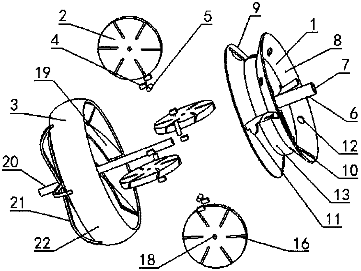
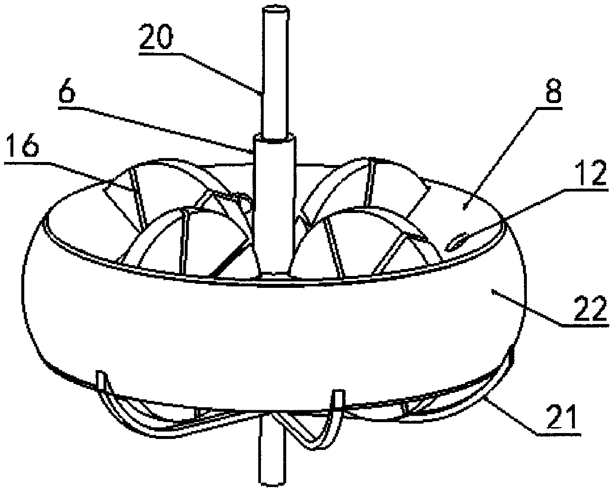
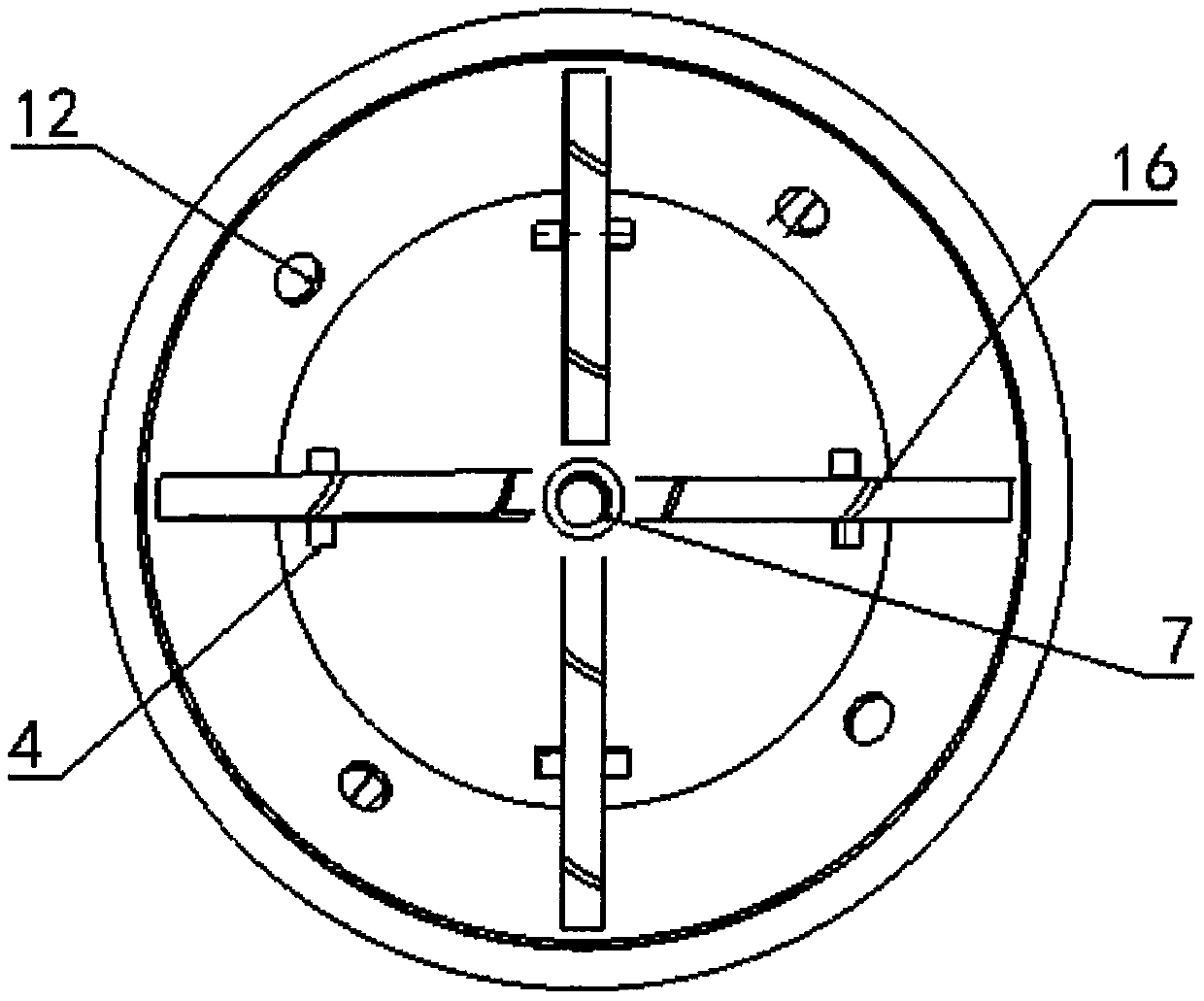
[0074] The rotating vane engagement type displacement mechanism of this embodiment is a structure suitable for vacuum machines and compressors. Through the engagement of the rotating vane 19 and the rotating plate 2, air inlet holes are respectively provided at the appropriate positions of the upper end cover 8 and the lower end cover 9. 12 and exhaust hole 11, in order to realize vacuuming or compressing the target equipment. Figure 1 to Figure 18 The vacuum machine is mainly used as an example for illustration. If it is to be converted into a compressor, the fixed shaft 6 needs to be arranged on the other side of the first intermediate fixed body 1, and the connecting rod 21 is arranged on the other side of the first peripheral rotating body 3, so that the One side of the air hole 12 is driven by the connecting rod 21 to rotate the rotating shell 22, and one side of the exhaust hole 11 is fixed and connected to the target equipme...

Embodiment 2

[0088] 1. Overall structure and appearance

[0089] The rotary vane meshing variable displacement mechanism of this embodiment is a structure suitable for a rotary engine. Through the engagement of the rotary vane 19 and the rotary plate 2, some through holes and rotary grooves are arranged on the rotary shell 22, and the second intermediate fixed body 27 Some through holes, baffles, air holes and igniters are arranged on the top to realize the four processes of suction, compression, ignition and exhaust, so as to promote the continuous rotation of the variable capacity mechanism. For the convenience of describing this embodiment clearly, the side including the fixed shaft 6 is marked as the front side, and the opposite side is marked as the back side.

[0090] Such as Figure 19 As shown, the general structure of the variable capacity mechanism of this embodiment is similar to that of Embodiment 1, mainly because the intermediate fixed body and the peripheral rotating body are...

Embodiment 3

[0115] 1. Overall structure and appearance

[0116] The rotating vane meshing variable displacement mechanism of this embodiment is a structure suitable for fluid dynamic machinery, similar to the ducted fan propeller, but the meshing rotation of the rotating vane and the rotating plate can transmit the rotational kinetic energy of the machine to the fluid to a greater extent. Compared with other fluid power machines, under the same rotation speed, the fluid can obtain a greater speed of movement perpendicular to the rotation plane. Applying this mechanism to the paddle part of ships, helicopters, etc., can obtain greater thrust than ordinary paddles.

[0117] Such as Figure 42 As shown, the general structure of the variable capacity mechanism of this embodiment is similar to that of Embodiment 1, mainly because of some differences in the middle fixing body, so it is named as the third middle fixing body 52 . After being assembled similarly to Embodiment 1, the upper plate ...


PUM


Abstract

A rotating vane-meshed type volume changing mechanism is disclosed. The mechanism can be used for compressors, vacuum machines, engines and various hydrodynamic force machines requiring formation of directional movement of fluids. The mechanism mainly includes middle fixed bodies, rotating plates and periphery rotating bodies. To achieve different functions, the middle fixed bodies at least have three different types and the periphery rotating bodies at least have two different types. The mechanism is characterized in that each of the middle fixed bodies is radially provided with at least tworotating-plate slots; the centers of the rotating plats are provided with rotation holes; and bolts pass through the rotation holes and the rotating plates are mounted in the rotating-plate slots. Therotating plates are radially provided with at least three inclined rotating vane meshing slots. The periphery rotating bodies are provided with rotating vanes the number of which is same as that of the rotating vane meshing slots. The rotating vanes have same degrees of inclination with the rotating vane meshing slots, and are meshed with the rotating plates through the rotating vane meshing slots. In a process that the rotating vanes and the rotating plates are meshed and rotate, a zone the size of which changes periodically is formed among the rotating vanes and the rotating plates.

Description

technical field [0001] The invention belongs to the field of fluid displacement mechanisms, and can be used for compressors, vacuum machines, engines and various fluid power machines that need to produce directional motion of fluid. Background technique [0002] The variable volume mechanism is one of the basic devices that utilize mechanical motion to realize periodic changes in space volume, and has a wide range of applications. According to the characteristics of periodic volume changes, the variable capacity mechanism can be used as a compressor, a vacuum machine, an engine, and various fluid power machines that need to produce directional motion of the fluid. [0003] At present, compressors and vacuum machines that rely on periodic changes in space volume are mainly divided into ten categories. The first type is the reciprocating piston type, which uses the reciprocating motion of the piston in the pump chamber to realize the periodic change of the closed space betwee...

Claims


Application Information

Patent Timeline
Patent Type & Authority Patents(China)
IPC IPC(8): F04C18/52F04C25/02F01C3/02F01C21/08F02B55/02F02B53/00
CPCF01C3/025F01C21/0809F02B53/00F02B55/02F04C18/52F04C25/02F04C2240/20Y02T10/12
Inventor 张银量
Owner 张银量
Learn More