Novel attenuation network

An attenuation network and a new type of technology, applied in the direction of measuring devices, instruments, digital variable display, etc., can solve problems that affect oscilloscope measurement, reduce measurement accuracy, and change the adjustment effect, so as to avoid uncontrollability and inconsistency, and speed up production. Efficiency, good adjustment effect

Active Publication Date: 2018-06-15
GUANGDONG MECHANICAL & ELECTRICAL COLLEGE
View PDF14 Cites 0 Cited by
  • Summary
  • Abstract
  • Description
  • Claims
  • Application Information

AI Technical Summary

Problems solved by technology

At present, the existing adjustable capacitors are all mechanically adjustable, and cannot be adjusted through a program. They must be adjusted manually. If they are manually adjusted, they must be adjusted before installing the shielding shell. However, the shielding shell itself will generate a certain amount of parasitic capacitance, so Even if the adjustment is done before installing the shielding case, after the shielding case is installed, the previous adjustment effect will change due to the addition of parasitic capacitance, which will eventually affect the measurement of the signal by the oscilloscope and reduce its measurement accuracy.

Method used


Image

  • Novel attenuation network
  • Novel attenuation network
  • Novel attenuation network

Examples


Embodiment 1

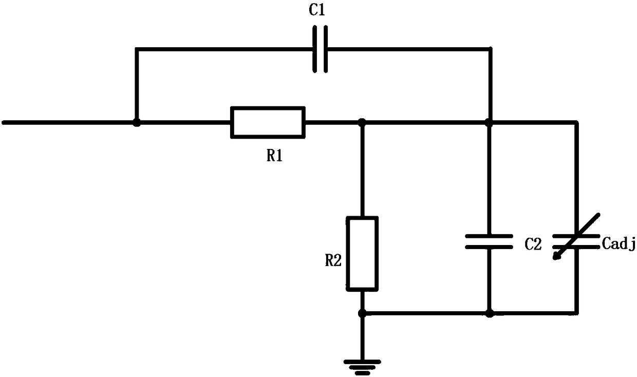
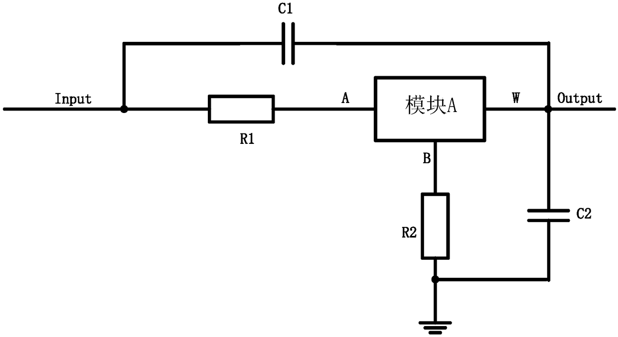
[0031] like figure 2 and image 3 As shown, the present invention discloses a new type of attenuation network. The composition of the attenuation network mainly includes the first resistor R1 and the second resistor R2 for low frequency voltage division, the first capacitor C1 and the second capacitor for high frequency voltage division. Capacitor C2, and the first module (namely module A) for adjusting the low frequency component. The first module includes three ports A, B, and W. The A port is connected to the signal input end through the first resistor R1. The B port is connected to the power ground GND (GND) through the second resistor R2. The W port is connected to the signal input end. Both ends of the first capacitor C1 are respectively connected to the signal input end and the signal output end. Both ends of the second capacitor C2 are respectively connected to the signal output terminal and the power ground GND.

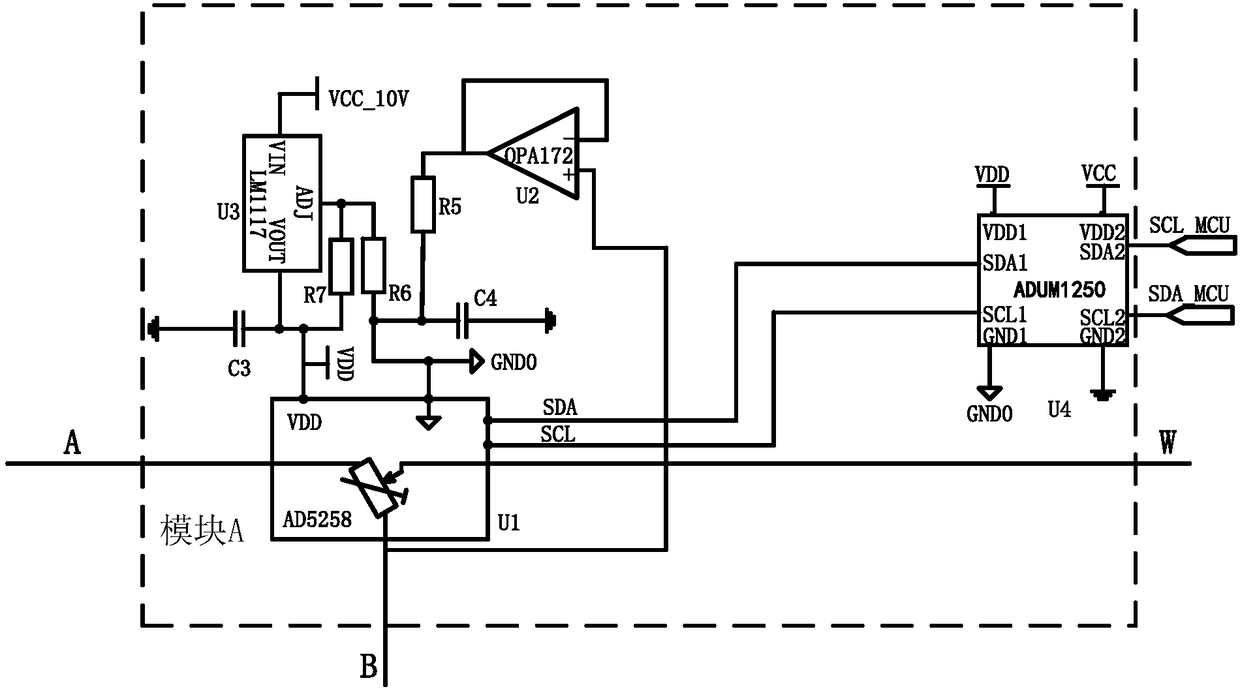
[0032] Specifically, the first module mainly in...

Embodiment 2

[0044] like figure 2 and image 3 As shown, the present invention discloses a new type of attenuation network used on an oscilloscope. The present invention uses a digital potentiometer to fine-tune the voltage division ratio of the resistance, connects both ends of the digital potentiometer to the attenuation resistor, and connects the middle tap to the On the capacitor and the post-stage circuit, so that the digital potentiometer can be programmed to change the resistance at both ends. At the same time, due to the characteristics of the digital potentiometer, the value of Rwa+Rwb is fixed, so this ensures that the input resistance of the attenuation network will not It changes with the adjustment of the digital potentiometer. The voltage division effect of the digital potentiometer produces two resistors Rwa and Rwb. By adjusting so that

[0045] (R2+Rwb) / (R1+Rwa)=C1 / C2. When the equation is established, the same effect as adjusting the capacitor can be achieved.

[00...


PUM


Abstract

The invention discloses a novel attenuation network comprising a first resistor, a second resistor, a first capacitor, a second capacitor and a first module. The A port is connected with the signal input end through the first resistor. The B port is connected with the power ground through the second resistor. The W port is connected with the signal input end. The two ends of the first capacitor are connected with the signal input end and the signal output end. The two ends of the second capacitor are connected with the signal output end and the power ground. A digital potentiometer is embeddedbetween the first resistor and the second resistor, and the constant voltage is provided to the digital potentiometer through a bootstrap boost unit. A two-way isolation isolator is also introduced to act as a driving chip for normally driving the digital potentiometer, and the external control side can conveniently control the digital potentiometer through the isolator so as to adjust the position of the sliding end of the internal adjustable resistor and acquire the better effect than that the prior art. The novel attenuation network also has the advantages of simple structure, low cost andconvenient adjustment.

Description

technical field [0001] The invention relates to the field of oscilloscopes, in particular to a novel attenuation network used in the oscilloscope to attenuate the amplitude of the signal to be measured. Background technique [0002] The internal circuit board of the existing oscilloscope generally uses a passive attenuation network to attenuate the amplitude of the signal to be measured, and its basic principle is the resistance voltage divider method. like figure 1 As shown, since the oscilloscope has a requirement of 1M input impedance, the resistance value of the voltage divider resistors is relatively large. Since the amplifier and PCB will have unavoidable parasitic capacitance, which will seriously affect the bandwidth of the oscilloscope, it is necessary to add a capacitor to compensate its bandwidth. According to its transfer function, it can be obtained that when C1 / (C2+Cadj)=R2 / R1, the poles and zeros cancel each other out, so that the bandwidth is flat. Among th...

Claims


Application Information

Patent Timeline
Patent Type & Authority Applications(China)
IPC IPC(8): G01R13/02
CPCG01R13/0209
Inventor 辛苗刘建圻赵静欧启标赵振廷
Owner GUANGDONG MECHANICAL & ELECTRICAL COLLEGE
Why Eureka
Try Eureka