River channel ecological monitoring system and method

An ecological monitoring and river channel technology, applied in the field of environmental research, can solve the problems of difficult data processing, large errors, and difficulty in obtaining quantitative indicators of fish.

Inactive Publication Date: 2018-06-15
GUANGXI UNIV +1
View PDF3 Cites 5 Cited by
  • Summary
  • Abstract
  • Description
  • Claims
  • Application Information

AI Technical Summary

Problems solved by technology

[0003] However, most of the current biological water quality monitoring systems that use fish as the monitoring object use cameras to observe and analyze changes in fish behavior to achieve water quality monitoring and early warning

Method used


Image

  • River channel ecological monitoring system and method
  • River channel ecological monitoring system and method
  • River channel ecological monitoring system and method

Examples


no. 1 example

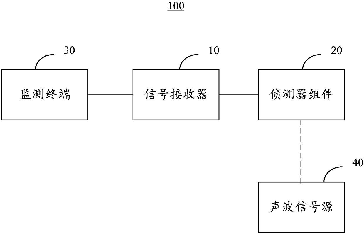
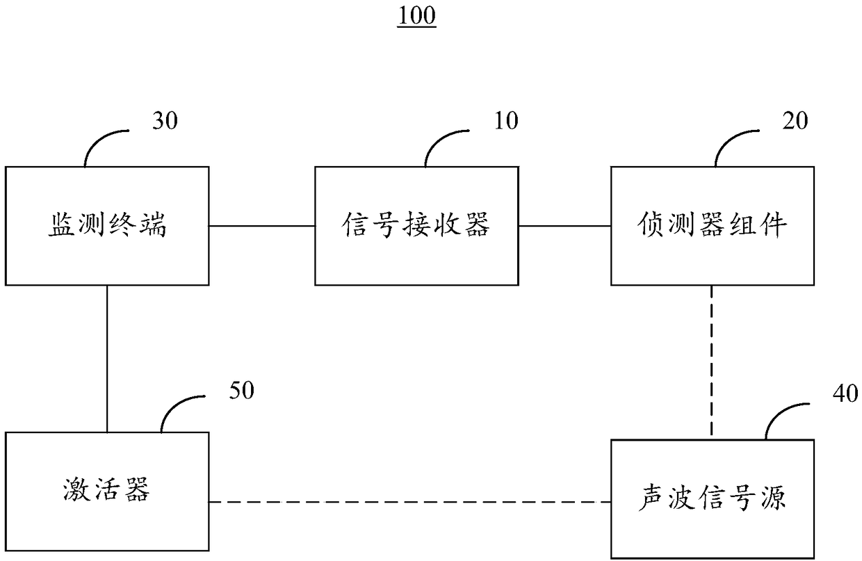
[0028] Please refer to figure 1 , figure 1 A schematic diagram of a river ecological monitoring system 100 is shown. The river ecological monitoring system 100 includes a signal receiver 10 , a detector component 20 , a monitoring terminal 30 and a plurality of acoustic signal sources 40 .

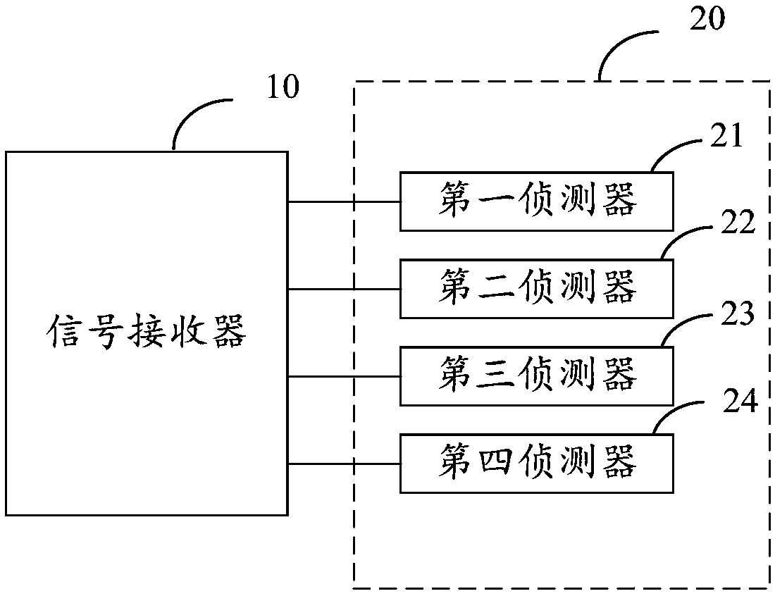
[0029] The signal receiver 10 is connected to the detector component 20 and the monitoring terminal 30 respectively, and the signal receiver 10 is used to receive the data sent by the detector component 20 and feed back the received data to the monitoring terminal 30 . The signal receiver 10 includes a plurality of data input interfaces. The signal receiver 10 is connected with the receiving detector component 20 through the above-mentioned data input interface.

[0030] The above-mentioned detector component 20 is used to receive the sound wave signals from all the sound wave signal sources 40 , and send the sound wave signals to the signal receiver 10 , and the signal receiver 10 send...

no. 2 example

[0040] Please refer to Figure 5 , Figure 5 A flow chart of the steps of a river channel ecological monitoring method provided by an embodiment of the present invention is shown. The method is applied to the monitoring terminal 30 in the river ecological monitoring system 100 provided in the first embodiment. The methods include:

[0041] Step S101 , receiving a sound wave signal sent by the signal receiver, the sound wave signal including a sound wave signal corresponding to at least one sound wave signal source 40 .

[0042] Step S102, performing noise removal processing on the received acoustic wave signal, and storing it.

[0043] Step S103 , classifying the stored sound wave signals according to the corresponding sound wave signal source 40 , wherein each type of sound wave signal corresponds to one of the sound wave signal sources 40 .

[0044] In the embodiment of the present invention, the sound wave signals sent by different sound wave signal sources 40 are also ...


PUM


Abstract

The embodiment of the invention provides a river channel ecological monitoring system and method, and relates to the technical field of water ecological environment research. A detector module in a system is installed in a monitoring water area, sound wave signal sources are fixed on fish bodies in the monitoring water area, a signal receiver is electrically connected with the detector module, thesignal receiver is connected with a monitoring terminal, the detector module is configured to receive sound wave signals corresponding to the sound wave signal sources and send the sound wave signalsto the signal receiver, the signal receiver forwards the received sound wave signals to the monitoring terminal, and the monitoring terminal performs processing of the sound wave signals to obtain atwo-dimensional track and a three-dimensional track corresponding to each sound wave signal source. The river channel ecological monitoring system and method can more accurately determine a state of afish group through the obtained tracks and can more accurately obtain behavior response indexes of the fish group for environment change so as to achieve more accurate monitoring of an ecological condition of a river channel where the fish group live. The river channel ecological monitoring system and method have very important meaning of the water ecological environment research.

Description

technical field [0001] The invention relates to the technical field of environmental research, in particular to a river channel ecological monitoring system and method. Background technique [0002] Fish organisms and their living environment are a unified whole, and the two are interdependent, mutually compensated, and co-evolved. Therefore, biological behavior monitoring has become an important means of monitoring, remediation, forecasting and evaluation of river pollution. The use of biomonitoring technology to establish a biotoxicity monitoring system for water environment safety is a research hotspot in environmental science at home and abroad. The behavioral responses of fish to changes in different environmental factors have also been extensively studied. [0003] However, most of the current biological water quality monitoring systems that use fish as the monitoring object use cameras to observe and analyze changes in fish behavior to achieve water quality monitorin...

Claims


Application Information

Patent Timeline
IPC IPC(8): G01S5/18G01N33/18A01K29/00
CPCA01K29/005G01N33/186G01S5/18
Inventor 黄月群蔡德所李明泉李烈吴攀高
Owner GUANGXI UNIV
Why Eureka
Try Eureka