A method for recording equipment usage time
A technology for recording equipment and time, applied to time registers, registering/indicating machine work, registering/indicating, etc., can solve the problem of inability to guarantee the reliability of elevator use, the inability to monitor elevator working hours, and increase the labor of maintenance personnel Strength and other issues, to achieve the effect of ensuring the reliability and safety of use, easy installation and strong applicability
- Summary
- Abstract
- Description
- Claims
- Application Information
AI Technical Summary
Problems solved by technology
Method used
Image

Examples
Embodiment 1
[0035] A method for recording device usage time, comprising the steps of:
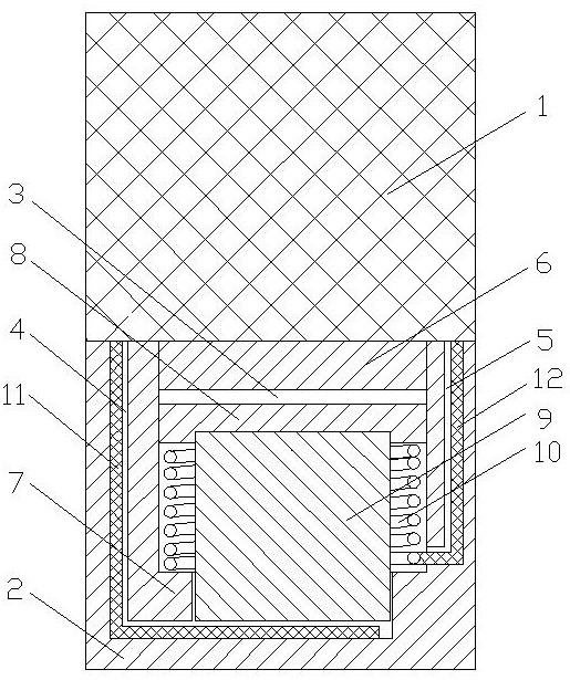
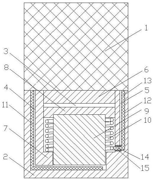
[0036] a. Install the smart module on the device, when the ferromagnetic object is close to the smart module, the magnet 9 in the smart module moves under the magnetic force and contacts with the conductor;
[0037] b. The chip 1 in the intelligent module recognizes that the conductor is connected, and starts to record the use time of the device;
[0038] c. When the ferromagnetic object is far away from the intelligent module, the magnet 9 is reset under the elastic force of the spring 10 in the intelligent module, the magnet 9 is separated from the conductor, the chip 1 recognizes that the conductor is disconnected, and the use time of the recording device is ended.
[0039] This embodiment is the most basic implementation mode, "a, the smart module is installed on the device, when the ferromagnetic object is close to the smart module, the magnet in the smart module moves under the action of magnetic...
Embodiment 2
[0041] A method for recording device usage time, comprising the steps of:
[0042] a. Install the smart module on the device, when the ferromagnetic object is close to the smart module, the magnet 9 in the smart module moves under the magnetic force and contacts with the conductor;
[0043] b. The chip 1 in the intelligent module recognizes that the conductor is connected, and starts to record the use time of the device;
[0044] c. When the ferromagnetic object is far away from the intelligent module, the magnet 9 is reset under the elastic force of the spring 10 in the intelligent module, the magnet 9 is separated from the conductor, the chip 1 recognizes that the conductor is disconnected, and the use time of the recording device is ended.
[0045] The intelligent module includes a chip 1 and a support 2, the chip 1 is fixed on the support 2, the inside of the support 2 has a mounting hole 3, a first wire channel 4 and a second wire channel 5, and the top of the mounting ho...
Embodiment 3
[0048] A method for recording device usage time, comprising the steps of:
[0049] a. Install the smart module on the device, when the ferromagnetic object is close to the smart module, the magnet 9 in the smart module moves under the magnetic force and contacts with the conductor;
[0050] b. The chip 1 in the intelligent module recognizes that the conductor is connected, and starts to record the use time of the device;
[0051] c. When the ferromagnetic object is far away from the intelligent module, the magnet 9 is reset under the elastic force of the spring 10 in the intelligent module, the magnet 9 is separated from the conductor, the chip 1 recognizes that the conductor is disconnected, and the use time of the recording device is ended.
[0052] The intelligent module includes a chip 1 and a support 2, the chip 1 is fixed on the support 2, the inside of the support 2 has a mounting hole 3, a first wire channel 4 and a second wire channel 5, and the top of the mounting ho...
PUM
 Abstract
Description
Claims
Application Information
 - R&D
- Intellectual Property
- Life Sciences
- Materials
- Tech Scout
- Unparalleled Data Quality
- Higher Quality Content
- 60% Fewer Hallucinations
Browse by: Latest US Patents, China's latest patents, Technical Efficacy Thesaurus, Application Domain, Technology Topic, Popular Technical Reports.
© 2025 PatSnap. All rights reserved.Legal|Privacy policy|Modern Slavery Act Transparency Statement|Sitemap|About US| Contact US: help@patsnap.com