Correction method, device and equipment used for optical sensor, and storage medium

A technology of light sensor and calibration method, which is applied in the field of calibration, can solve the problems of different backlight brightness, slow increase or decrease of backlight brightness, different problems, etc., and achieve the effect of consistent backlight brightness

Inactive Publication Date: 2018-06-15
GUANGDONG XIAOTIANCAI TECH CO LTD
View PDF9 Cites 21 Cited by
  • Summary
  • Abstract
  • Description
  • Claims
  • Application Information

AI Technical Summary

Problems solved by technology

However, because multiple devices of the same model were not calibrated under the same lighting environment in advance, multiple devices of the same model with the automatic brightness adjustment function turned on showed different backlight brightness in the same lighting environment.
However, if a user owns these devices at the same time, he will have doubts about the quality of the device due to the difference in backlight brightness, which will greatly affect the user experience.
[0003] In the prior art, in order to solve the problem that the same type of equipment may display different backlight brightness under the same lighting environment, the usual method is to slowly increase or decrease the backlight brightness so that users can adapt to the backlight brightness, but still Unable to fundamentally solve the problem of differences between different devices

Method used


Image

  • Correction method, device and equipment used for optical sensor, and storage medium
  • Correction method, device and equipment used for optical sensor, and storage medium
  • Correction method, device and equipment used for optical sensor, and storage medium

Examples


Embodiment 1

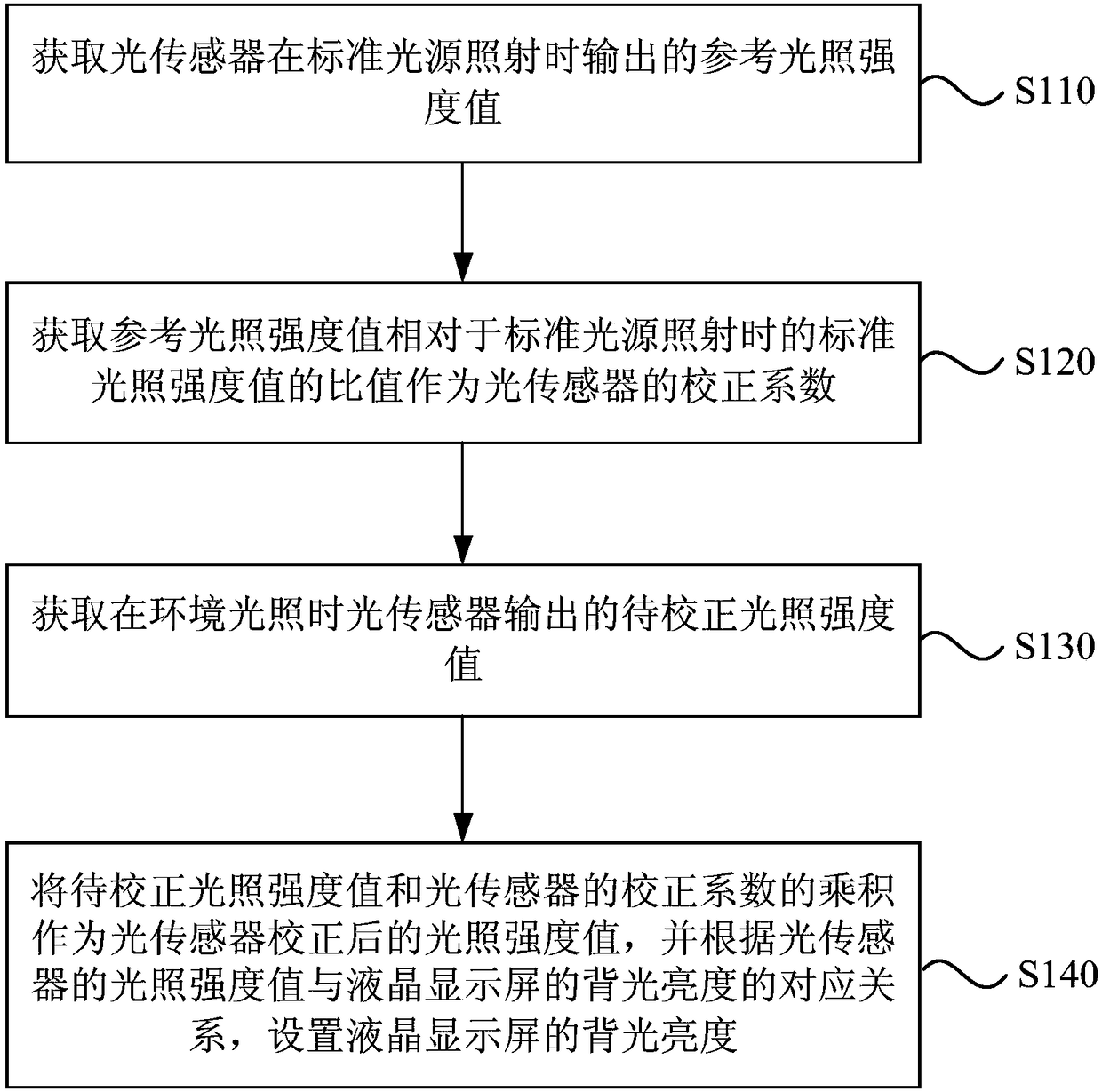
[0045] figure 1 It is a flow chart of a calibration method for a light sensor provided by Embodiment 1 of the present invention. This embodiment is applicable to the situation of adjusting a light sensor, and the method can be performed by a calibration device for a light sensor. The device can Implemented in the form of software and / or hardware, the device can be configured in equipment, such as typically mobile phones, tablet computers, and computers. Such as figure 1 As shown, the method specifically includes the following steps:

[0046] S110. Obtain a reference light intensity value output by the light sensor when irradiated by a standard light source;

[0047] In a specific embodiment of the present invention, the standard light source may refer to an artificial light source that simulates various ambient lighting conditions, so that the off-site production factory or laboratory can obtain lighting effects that are basically consistent with the light source in these sp...

Embodiment 2

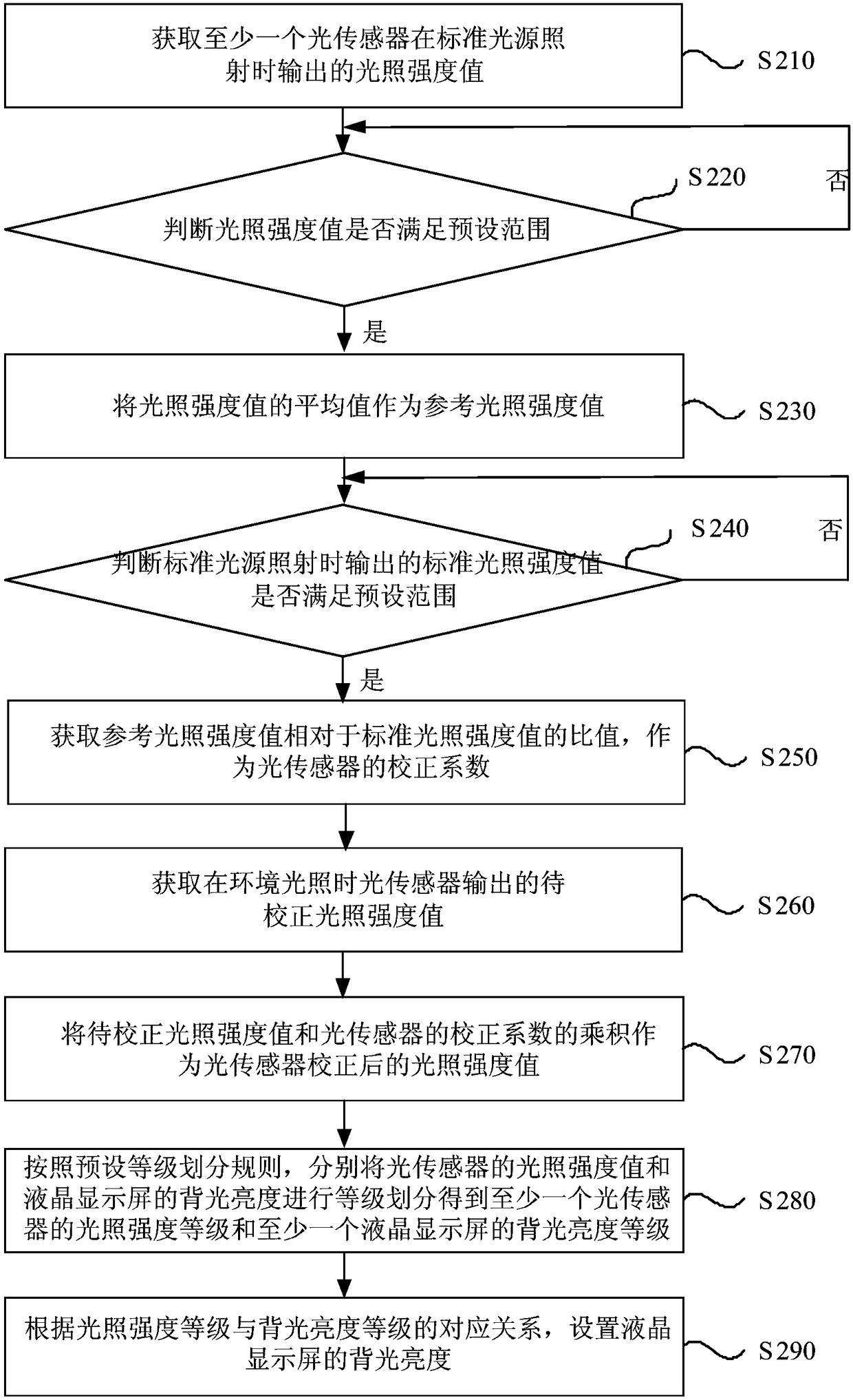
[0078] figure 2 It is a flow chart of a calibration method for a light sensor provided in Embodiment 2 of the present invention. This embodiment is applicable to the situation of adjusting a light sensor. The method can be performed by a calibration device for a light sensor. The device can Implemented in the form of software and / or hardware, the device can be configured in equipment, such as typically mobile phones, tablet computers, and computers. Such as figure 2 As shown, the method specifically includes the following steps:

[0079] S210. Obtain the light intensity value output by at least one light sensor when illuminated by a standard light source;

[0080] S220. Determine whether the light intensity value satisfies the preset range; if yes, execute S230; if not, continue to execute S220;

[0081] S230. Using the average value of the light intensity values ​​as a reference light intensity value;

[0082] S240. Judging whether the standard light intensity value out...

Embodiment 3

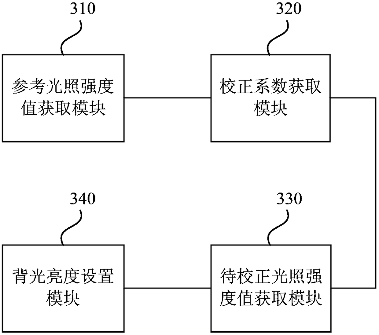
[0092] image 3 It is a schematic structural diagram of a calibration device for optical sensors provided by Embodiment 3 of the present invention. This embodiment is applicable to the situation of adjusting optical sensors. The device can be realized by software and / or hardware, and the device can be configured in devices such as mobile phones, tablets, and computers. Such as image 3 As shown, the device specifically includes:

[0093] A reference light intensity value acquisition module 310, configured to acquire a reference light intensity value output by the light sensor when illuminated by a standard light source;

[0094] The correction coefficient acquisition module 320 is used to obtain the ratio of the reference light intensity value relative to the standard light intensity value when the standard light source is irradiated, as the correction coefficient of the light sensor;

[0095] The light intensity value to be corrected acquisition module 330 is used to obtai...


PUM


Abstract

The invention discloses a correction method, a device and equipment used for an optical sensor, and a storage medium. The method comprises the following steps of acquiring a reference illumination intensity value output by the optical sensor under standard light source irradiation; acquiring the ratio of the reference illumination intensity value relative to a standard illumination intensity valueunder the standard light source irradiation and taking as the correction coefficient of the optical sensor; acquiring an illumination intensity value to be corrected output by the optical sensor under environment illumination; and taking the product of the illumination intensity value to be corrected and the correction coefficient of the optical sensor as the corrected illumination intensity value of the optical sensor, and according to the corresponding relation of the illumination intensity value of the optical sensor and the backlight brightness of a liquid crystal display screen, adjusting the backlight brightness of the liquid crystal display screen so that the optical sensor outputs the corrected illumination intensity value under the environment illumination. In the invention, a problem that the backlight brightness of the same model of equipment under a same illumination environment is not consistent is solved, and the backlight brightness of the equipment under the same illumination environment is consistent.

Description

technical field [0001] Embodiments of the present invention relate to a calibration technology, and in particular, to a calibration method, device, equipment and storage medium for an optical sensor. Background technique [0002] At present, in the electronic product market, most devices have automatic brightness adjustment functions, which are realized by light sensors. However, because multiple devices of the same model were not calibrated under the same lighting environment in advance, multiple devices of the same model with the automatic brightness adjustment function turned on showed different backlight brightness under the same lighting environment. However, if a user owns these devices at the same time, they will doubt the quality of the device due to the difference in backlight brightness, which greatly affects the user experience. [0003] In the prior art, in order to solve the problem that the same type of equipment may display different backlight brightness unde...

Claims


Application Information

Patent Timeline
Patent Type & Authority Applications(China)
IPC IPC(8): G09G3/34
CPCG09G3/3406G09G3/3413
Inventor 李远强
Owner GUANGDONG XIAOTIANCAI TECH CO LTD
Why Eureka
Try Eureka