
Magnetic resonance hospital bed horizontal motion driving structure

A magnetic resonance bed, horizontal motion technology, applied in medical science, sensors, diagnostic recording/measurement, etc., can solve problems such as electromagnetic interference, affecting imaging quality, and large power, eliminating electromagnetic interference, simplifying shielding structure, reducing The effect of push and pull

Pending Publication Date: 2018-06-19
ALLTECH MEDICAL SYST
View PDF7 Cites 2 Cited by
  • Summary
  • Abstract
  • Description
  • Claims
  • Application Information

AI Technical Summary

Problems solved by technology

[0003] In the scanning of MRI equipment, due to the vibration of the gradient coil, the bed plate may move slightly in the Z-axis direction, and the holding torque of the servo motor after power-on cannot guarantee that the motor shaft will not rotate, especially it cannot prevent the motor shaft from rotating at a small angle. , and the movement of the bed board caused by this small angular motion has a great influence on the imaging; secondly, if the bed board uses the motor to maintain the torque to keep the bed board position constant, it will connect the power supply and control signal to the motor, and this will bring electromagnetic interference problems , affect the imaging quality, in order to solve the electromagnetic interference, it will take a lot of effort to do shielding measures, and then put forward requirements for the available space; finally, the bed board and the horizontal motion drive mechanism cannot be separated, and the horizontal motion mechanism has various levels of reducers The existence of the existence and the energy loss in the transmission at all levels, in special cases, the force is very large when it is used to push and pull the hospital bed

Method used


Image

  • Magnetic resonance hospital bed horizontal motion driving structure
  • Magnetic resonance hospital bed horizontal motion driving structure
  • Magnetic resonance hospital bed horizontal motion driving structure

Examples


Embodiment Construction

[0021] In order to make the object, technical solution and advantages of the present invention clearer, the present invention will be further described in detail below in conjunction with the accompanying drawings.

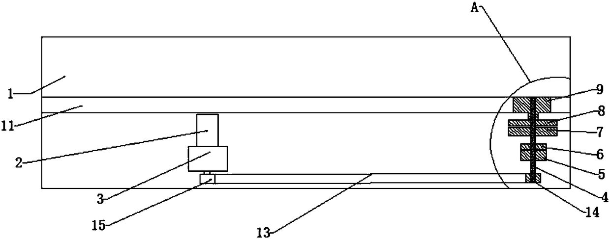
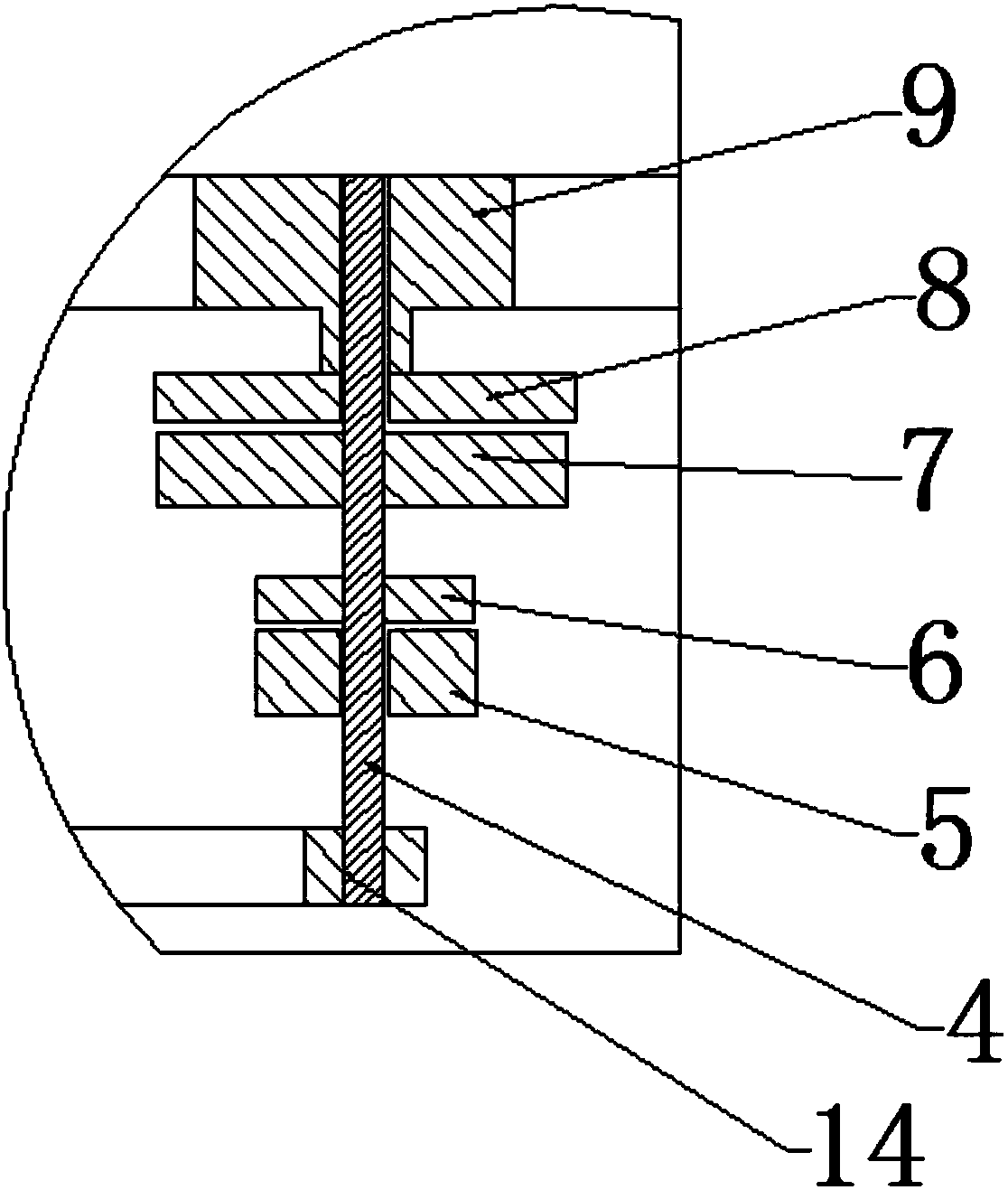
[0022] like figure 2 , 3 , 4, the magnetic resonance hospital bed horizontal motion drive structure disclosed by the present invention includes a bed board 1, a motor 2, a reducer 3, a transmission mechanism, a through shaft 4, a brake component A5, a brake component B6, a clutch component A7, and a clutch component B8 , driving gear 9 and driven gear 10, rack 11 is installed at the bottom of described bed board 1;

[0023] The motor 2 is installed on the main body 12 of the hospital bed, and the motor 2 is a servo motor. The reducer 3 is directly connected in series with the output shaft of the motor 2, the output shaft of the reducer 3 is equipped with an active synchronous wheel 15, and the active synchronous wheel 15 transmits power to the driven synchronou...


PUM


Abstract

The invention relates to a magnetic resonance hospital bed horizontal motion driving structure. The structure comprises a bed plate, a motor, a speed reducer, a transmission mechanism, a through shaft, a brake component A, a brake component B, a clutch component A, a clutch component B, a driving gear and a driven gear, and a rack is mounted on the bottom of the bed plate; the speed reducer is connected to the output shaft of the motor, and the speed reducer is connected to the through shaft through the transmission mechanism; the brake component A is fixed to a hospital bed body, and the brake component A, the clutch component B and the driving gear are matched with the gap of the through shaft; the brake member B and the clutch member A are both fixed to the through shaft, the clutch member B and the driving gear are fixed, the driving gear meshes with the driven gear, and the driven gear meshes with the rack. The structure ensures that the position of the Z-axis direction of the bedplate is fixed during the magnetic resonance scanning process through the design of a brake lock mechanism and a clutch, eliminates an electromagnetic interference problem of a servo motor system, simplifies a shielding structure, reduces costs, and simultaneously reduces push and pull force when the bed plate is pushed and pulled manually.

Description

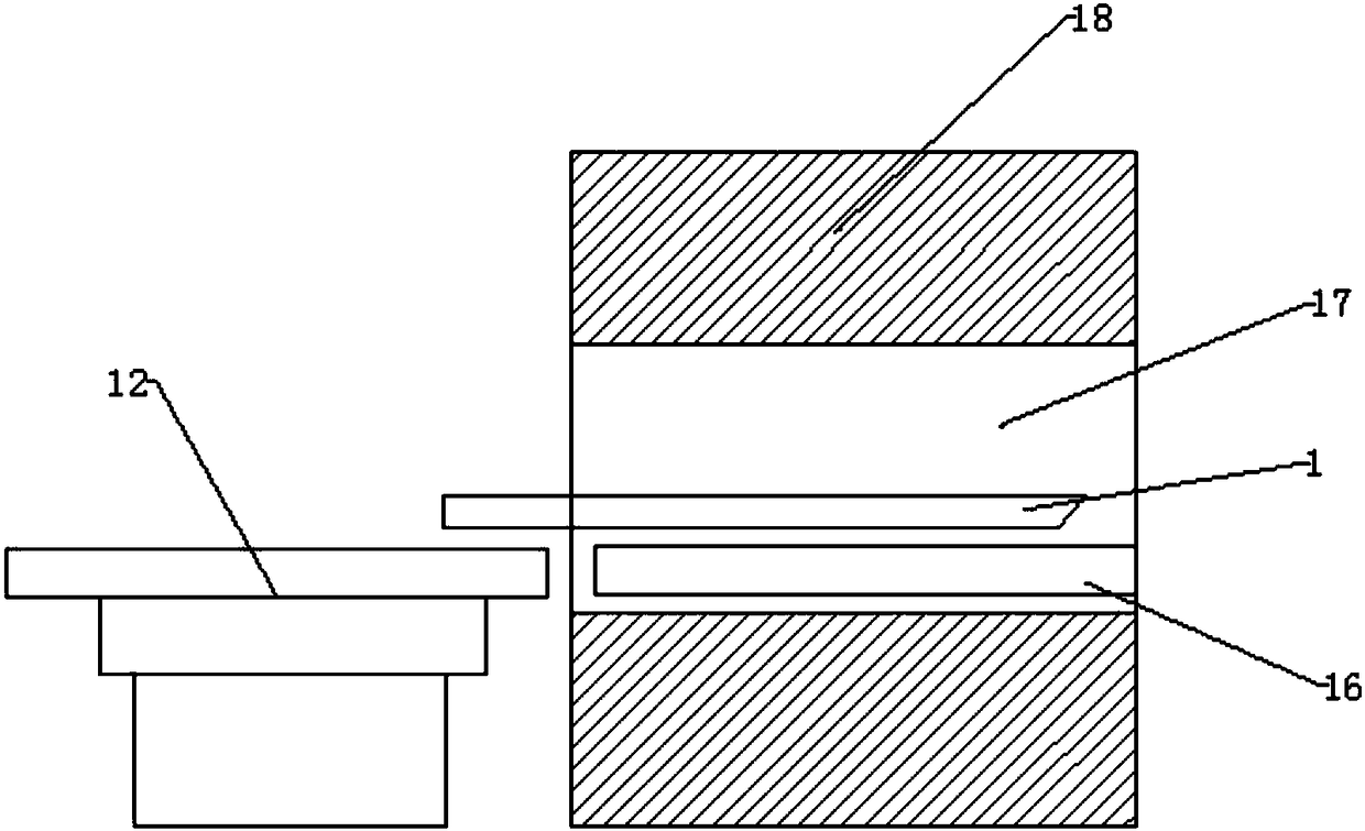
technical field [0001] The invention relates to the technical field of magnetic resonance imaging equipment, in particular to a horizontal motion driving structure of a magnetic resonance hospital bed. Background technique [0002] In a magnetic resonance imaging facility, the patient bed is used to carry the patient into and out of the scanning chamber (number 17) of the magnet (number 18). like figure 1 As shown, the hospital bed mainly includes a bed main body (serial number 12) that can move up and down and a bed board (serial number 1) that can move horizontally, and bed board guide rails (serial number 16) are provided in the scanning cavity. At present, the horizontal drive of the bed board is driven by the servo motor according to the program control requirements, and the horizontal movement of the bed board is realized through the drive of the rack and pinion or the synchronous belt of the synchronous wheel. After the bed board enters the magnet scanning area, the...

Claims


Application Information

Patent Timeline
Patent Type & Authority Applications(China)
IPC IPC(8): A61B5/055
CPCA61B5/055
Inventor 陈宏赵勇龚德华刘春宝
Owner ALLTECH MEDICAL SYST
Learn More