Head-mounted three-dimensional electronic operation microscope system

A surgical microscope and stereoscopic microscope technology, applied in the field of head-mounted three-dimensional electronic surgical microscope system, can solve the problems of operator fatigue, loss in the medical field, and low flexibility of the microscope, and achieve high-delay video effects, good economy and Social benefits, strengthening the effect of dissemination, learning and communication

Inactive Publication Date: 2018-06-19
上海瑞烁信息科技有限公司
View PDF0 Cites 4 Cited by
  • Summary
  • Abstract
  • Description
  • Claims
  • Application Information

AI Technical Summary

Problems solved by technology

After years of development, the plane stereo microscope has many technologies that are very mature, but the observation of the sample can only be done in a vertical direction, and the sample cannot be observed from multiple angles.
Microsurgery is an important part of modern surgery. The key equipment for microsurgery (including otology, ophthalmology, neurosurgery and plastic surgery, etc.) Closely align and stare at the eyepiece for micromanipulation, which not only makes the operator prone to fatigue, but also often causes cervical and lumbar strain
[0003] The traditional 3D surgical microscope has a single function and is only suitable for the human eye to observe objects directly through the optical eyepiece of the microscope. It takes two to three hours to do one long operation, which is not conducive to the doctor's health
[0004] Traditional surgical microscopes can usually only be viewed by one person or two people at the same time, and there are the following technical defects: Doctors who perform surgery are required to have rich experience, and for new doctors, it is far away to observe real cases; rapid development in the information age Today, information dissemination is particularly important. As the largest carrier, the Internet will be a great loss to the medical community if it is not utilized.

Method used


Image

  • Head-mounted three-dimensional electronic operation microscope system
  • Head-mounted three-dimensional electronic operation microscope system

Examples


Embodiment Construction

[0014] The present invention will be further described below in conjunction with accompanying drawing, but not as limiting the present invention:

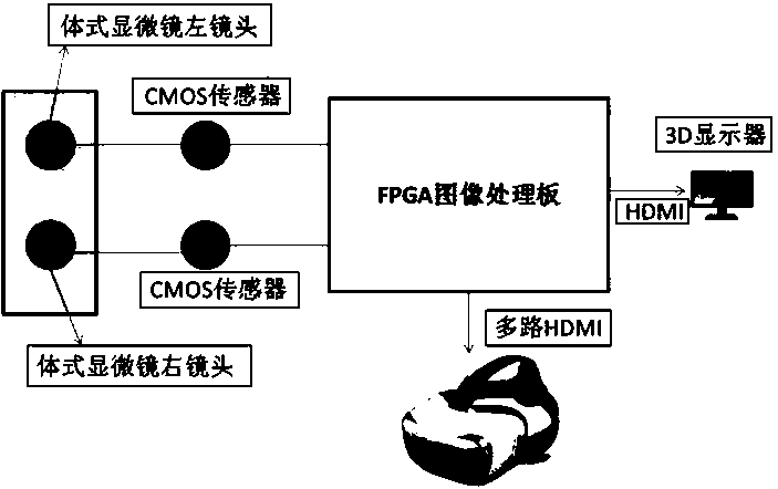
[0015] A head-mounted three-dimensional electronic surgical microscope system, including an FPGA image processing board, is characterized in that: the input terminal of the FPGA image processing board has two inputs, and one route is through the left lens of the stereo microscope through its built-in CMOS sensor A and FPGA The input terminal A of the image processing board is connected, and the right lens of the stereo microscope is connected to the input terminal B of the FPGA image processing board through its built-in CMOS sensor B; the output terminal of the FPGA image processing board is divided into two outputs, one of which is connected to the 3D display through HDMI , and the other is connected to the VR display through multiple HDMI channels; the CMOS sensor A and the CMOS sensor B both use two 2-megapixel high-definition C...


PUM


Abstract

The invention discloses a head-mounted three-dimensional electronic operation microscope system. The head-mounted three-dimensional electronic operation microscope system comprises an FPGA image processing board, the input end of the FPGA image processing board has two-path inputs, one path is that a left lens of a stereomicroscope is connected with the input end A of the FPGA image processing board through a CMOS sensor A arranged inside the stereomicroscope, and the other path is that a right lens of the stereomicroscope is connected with the input end B of the FPGA image processing board through a CMOS sensor B arranged inside the stereomicroscope; the output end of the FPGA image processing board has two-path outputs, one path is connected with a 3D display through an HDMI, and the other path is connected with a VR display through a multipath HDMI. By means of the head-mounted three-dimensional electronic operation microscope system, through the combination of software and hardwareand an optical mode, people clean clearly display three-dimensional images through a head-mounted display system, the imaging effect is very obvious, and the display speed can achieve the real-time effect.

Description

technical field [0001] The invention belongs to the technical field of medical equipment, in particular to a head-mounted three-dimensional electronic surgical microscope system. Background technique [0002] A microscope is an optical instrument composed of a lens or a combination of multiple lenses, which is used to magnify and image tiny objects. After many years of development of the plane stereo microscope, many technologies have been very mature, but the observation of the sample can only be done in a vertical direction, and the sample cannot be observed from multiple angles. Microsurgery is an important part of modern surgery. The key equipment for microsurgery (including otology, ophthalmology, neurosurgery and plastic surgery, etc.) Close alignment and staring at the eyepiece for micromanipulation not only makes the operator prone to fatigue, but also often causes cervical and lumbar strain. [0003] The traditional 3D surgical microscope has a single function and...

Claims


Application Information

Patent Timeline
Patent Type & Authority Applications(China)
IPC IPC(8): A61B90/20
CPCA61B90/20
Inventor 彭剑
Owner 上海瑞烁信息科技有限公司
Why Eureka
Try Eureka