
A filter element and a filter device using the filter element

A filter device and filter element technology, which is applied in the direction of fixed filter element filter, filter separation, membrane filter, etc., can solve the problems of filter mesh damage, affecting welding quality, etc., and achieve the effect of enhancing strength

Active Publication Date: 2020-09-11
新乡平原航空液压设备有限公司
View PDF5 Cites 0 Cited by
  • Summary
  • Abstract
  • Description
  • Claims
  • Application Information

AI Technical Summary

Problems solved by technology

For example, the authorized announcement number is CN206008301U, and the name is a Chinese patent for a filter device and its filter element. The filter device includes a filter element. One side is the fluid inlet side, and the other side is the fluid outlet side. The fluid outlet side of the filter screen is provided with a skeleton for supporting the filter screen. Two filter parts, the first filter part and the second filter part include at least one layer of filter screen, the skeleton and each filter screen are superimposed on each other and the two ends are basically flush, and the two ends of the skeleton and the filter screen are respectively connected with left end covers (equivalent to The first end cover) and the right end cover (equivalent to the second end cover), the left and right end covers and the frame and filter screen are generally welded by lap joints, and the ends of the frame and filter screen are set on the steps of the end cover surface, and the ends of the skeleton and the filter mesh are abutted against the stepped surface of the end cover, and the skeleton and the filter mesh are fixed relative to the end cap by welding at the abutment fit, because the molten pool is between the filter mesh and the skeleton During the welding process, the liquid metal in the molten pool tends to flow onto the filter screen between the end of the tube and the stepped surface of the corresponding end cap, which will cause damage to the filter screen and affect the welding quality

Method used


Image

  • A filter element and a filter device using the filter element
  • A filter element and a filter device using the filter element
  • A filter element and a filter device using the filter element

Examples


Embodiment Construction

[0022] Embodiments of the present invention will be further described below in conjunction with the accompanying drawings.

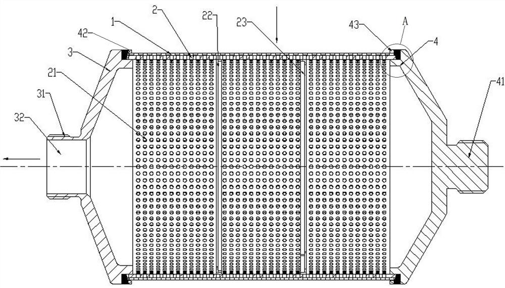
[0023] A specific embodiment of the first filtering device of the present invention: the filtering device includes a housing and a filter element, such as figure 1 As mentioned above, the filter element includes a cylindrical filter screen 1 whose axis extends along the left and right directions, the outer side of the filter screen 1 along the radial direction is the fluid inlet side, and the inner side of the filter screen 1 along the radial direction is the fluid outlet side. The fluid outlet side of the filter screen 1 (that is, the inner side of the filter screen along the radial direction in this embodiment) is provided with a framework 2 for supporting the filter screen.

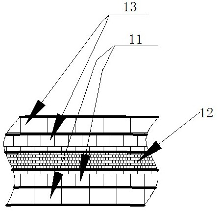
[0024] Such as figure 2 As mentioned above, the filter screen includes a first filter part 11 , a second filter part 12 and a third filter part 13 which are sequentially arrang...


PUM


Abstract

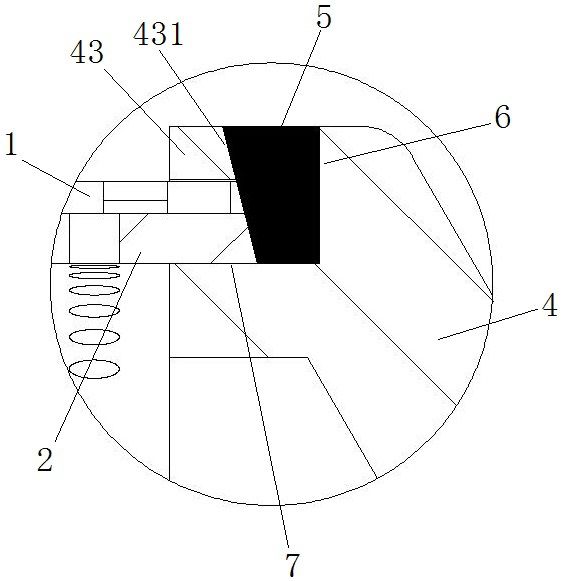
The invention relates to a filter core and a filter device using the same. The filter device consists of a shell and a filter core, the filter core includes a cylindrical filter screen, the inner sideor outer side of the filter screen is equipped with a skeleton for supporting the filter screen along the radial direction, and the other side is equipped with liquid metal retaining rings at the ends, two ends of the filter screen are respectively connected to a first end cover and a second end cover, during welding, a liquid metal formed at the ends of the filter screen is blocked by the liquidmetal retaining rings and cannot flow toward the middle of the filter screen along the axial direction, thereby preventing the liquid metal from flowing to the filtration part of the filter screen tocause filter screen blockage and other problems resulting in abnormal use of the filter screen. At the same time, the liquid metal retaining rings also can play the role of fixing and compressing thefilter screen and enhancing the strength of the skeleton.

Description

technical field [0001] The invention relates to a filter core and a filter device using the filter core. Background technique [0002] The filter element is a device for filtering impurities in the fluid. For example, the authorized announcement number is CN206008301U, and the name is a Chinese patent for a filter device and its filter element. The filter device includes a filter element. One side is the fluid inlet side, and the other side is the fluid outlet side. The fluid outlet side of the filter screen is provided with a skeleton for supporting the filter screen. Two filter parts, the first filter part and the second filter part include at least one layer of filter screen, the skeleton and each filter screen are superimposed on each other and the two ends are basically flush, and the two ends of the skeleton and the filter screen are respectively connected with left end covers (equivalent to The first end cover) and the right end cover (equivalent to the second end c...

Claims


Application Information

Patent Timeline
Patent Type & Authority Patents(China)
IPC IPC(8): B01D29/11B01D29/13
CPCB01D29/111B01D29/13B01D2201/0415
Inventor 张中明刘绍斌胡振磊田英方亚松张怀昭谢宪旺
Owner 新乡平原航空液压设备有限公司
Learn More