
Hardware piece vertical bending process

A hardware and vertical bending technology, applied in the field of hardware vertical bending technology, can solve the problems of waste of resources, excessive bending of pipe fittings, high labor intensity, etc., and achieve the effect of consistent angle, improved bending accuracy, and improved efficiency.

Inactive Publication Date: 2018-06-19
艾里芸(重庆)品牌营销策划有限公司
View PDF4 Cites 0 Cited by
  • Summary
  • Abstract
  • Description
  • Claims
  • Application Information

AI Technical Summary

Problems solved by technology

The traditional bending method is manual bending, but the labor intensity is relatively high; in order to reduce the labor intensity, the current bending of steel bars usually adopts mechanical bending, that is, the pipe fittings are placed on the support table and the bending plate, and the bending plate is driven by a motor. Rotate to bend the pipe fittings. After one pipe fitting is bent, the pipe fitting is removed, and then the motor drives the bending plate to reset, and then the next pipe fitting is bent.
However, this bending method still has the following two defects: 1. Since the next pipe can only be bent after the bending plate is reset, the efficiency of this bending method is low in view of the large demand for bent pipes; 2. . Since the motor drives the bending plate to rotate to realize the bending of the pipe fittings, after reaching the bending angle, the motor cannot stop rotating in an instant, which will lead to excessive bending of the pipe fittings. For pipe fittings that require high bending angle accuracy , Excessively bent pipe fittings are scrap products, resulting in waste of resources

Method used


Image

  • Hardware piece vertical bending process
  • Hardware piece vertical bending process
  • Hardware piece vertical bending process

Examples


Embodiment Construction

[0024] The following is a further detailed description through specific implementations:

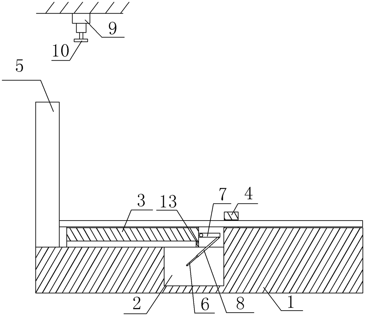
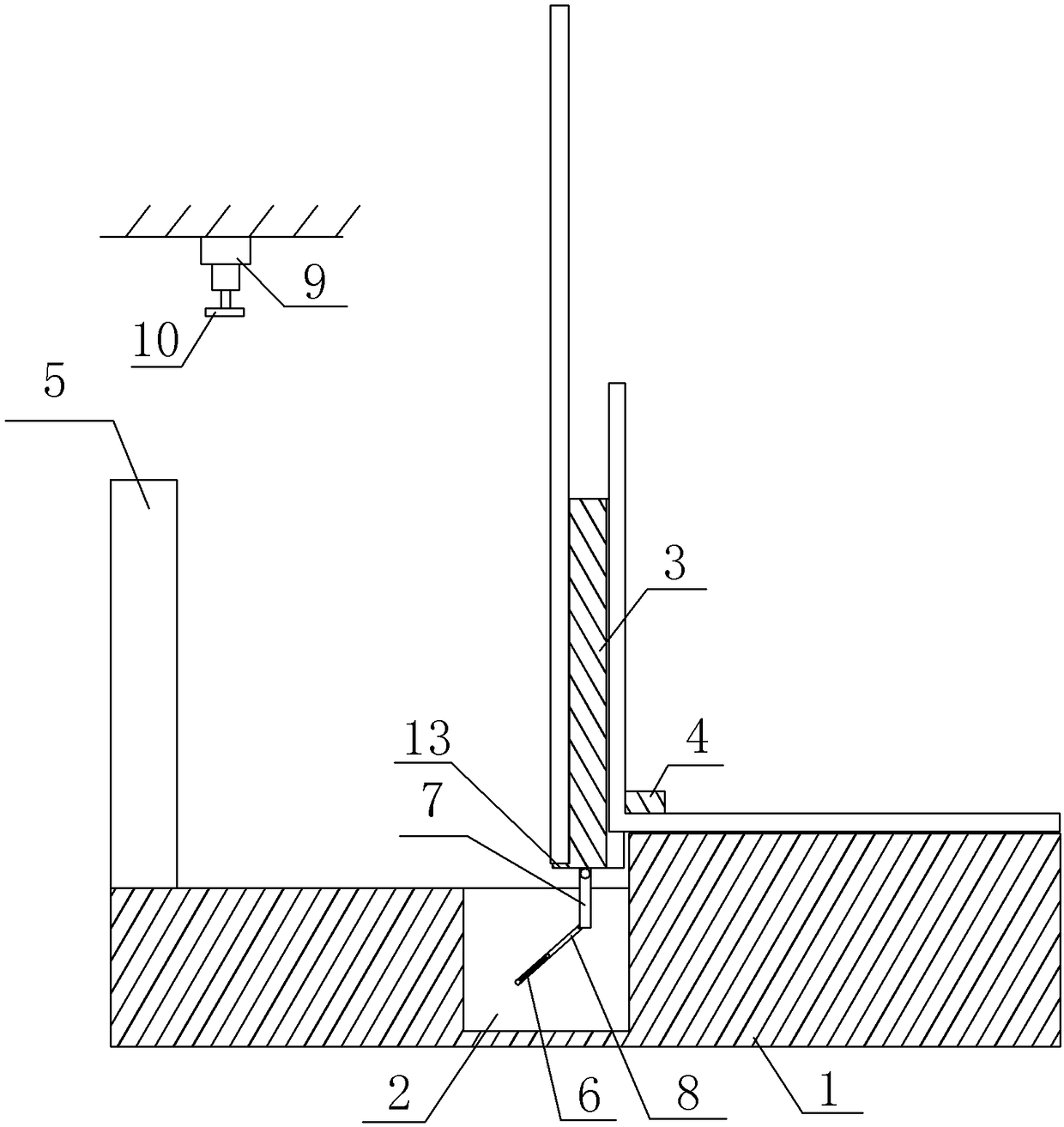
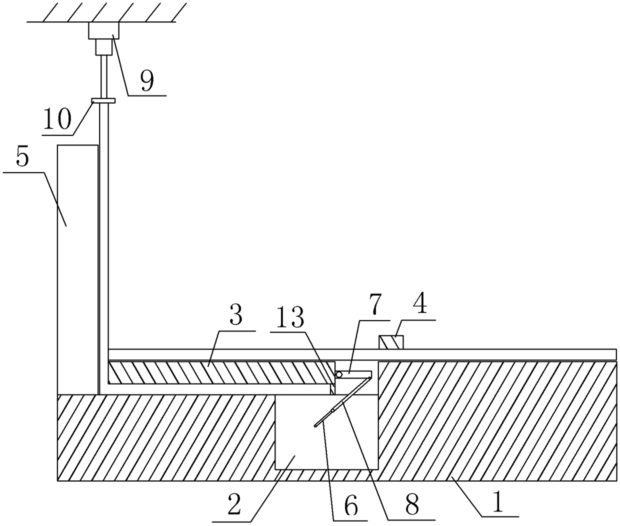
[0025] The reference signs in the drawings of the specification include: support table 1, groove 2, bending strip 3, clamping block 4, bending baffle 5, driving rod 6, driven rod 7, connecting rod 8, cylinder 9, The abutment plate 10, the first arc groove 11, the second arc groove 12, the stopper 13, the strip groove 14, the tension spring 15, and the fastening piece 16.

[0026] A hardware vertical bending process specifically includes the following steps:

[0027] Step 1: Prepare a figure 1 The hardware vertical bending equipment shown includes a supporting table 1 and a bending mechanism. The supporting table 1 is stepped and includes a first table on the left and a second table on the right. A groove 2 is opened on the first table.

[0028] The bending mechanism includes a motor, a crank and rocker unit, a bending strip 3, a clamping block 4 and a bending baffle 5. The motor is located in ...


PUM


Abstract

The invention relates to the field of pipe bending, and concretely relates to a hardware piece vertical bending process, which comprises the following steps of (1) preparing a hardware piece verticalbending device; (2) placing a first pipe; (3) bending the first pipe, and placing a second pipe; (4) bending a second pipe, and taking the first pipe down; (5) pressing against the second pipe, and placing a third pipe; and (6) bending the third pipe, and taking the second pipe down. By adopting the technical scheme, the bending efficiency and the bending accuracy of the pipes are improved.

Description

Technical field [0001] The invention relates to the field of pipe bending, in particular to a vertical bending process for hardware. Background technique [0002] Pipe fittings are widely used in industries such as automobiles, ships, aerospace, aviation, electrical appliances, agriculture, electromechanical, household appliances, etc. For installation or other use needs, the pipe fittings need to be bent to make it in an "L" shape, so it is also called vertical bending. The traditional bending method is manual bending, but the labor intensity is relatively high; in order to reduce labor intensity, the current steel bending usually adopts mechanical bending, that is, the pipe is placed on the support table and the bending plate, and the bending plate is driven by the motor. Rotate to bend the pipe fittings. After one pipe fitting is bent, the pipe fittings are removed, and then the motor drives the bending plate to reset, and then the next pipe fitting is bent. However, this ben...

Claims


Application Information

Patent Timeline
Patent Type & Authority Applications(China)
IPC IPC(8): B21D43/00B21D7/024B21D7/16
CPCB21D43/003B21D7/024B21D7/16
Inventor 廖洪平
Owner 艾里芸(重庆)品牌营销策划有限公司
Learn More