Automatic stacking device on bagged material loading machine

The technology of a stacking device and a car loader is applied in the field of material conveying equipment, which can solve the problems such as the inability to realize the vertical and horizontal mixed alternate arrangement, the inability to meet the requirements of automatic loading, and the limited use conditions of the car loader, so as to reduce labor The effect of labor intensity, reducing dust pollution and simple structure

Active Publication Date: 2018-06-19
CNBM HEFEI POWDER TECH EQUIP CO LTD +1
View PDF15 Cites 7 Cited by
  • Summary
  • Abstract
  • Description
  • Claims
  • Application Information

AI Technical Summary

Problems solved by technology

However, this loading machine can only realize the horizontal linear arrangement of bagged cement bales, and cannot meet the requirements of vertical and horizontal mixing and alternate placement of materials, and the stacking stability is poor. It will greatly exceed the compartment baffle, which greatly increases the risk of long-distance transportation, and the loading machine has limited use conditions, and cannot meet the automatic loading requirements of any bag size automatically adapting to various specifications of vehicles

Method used

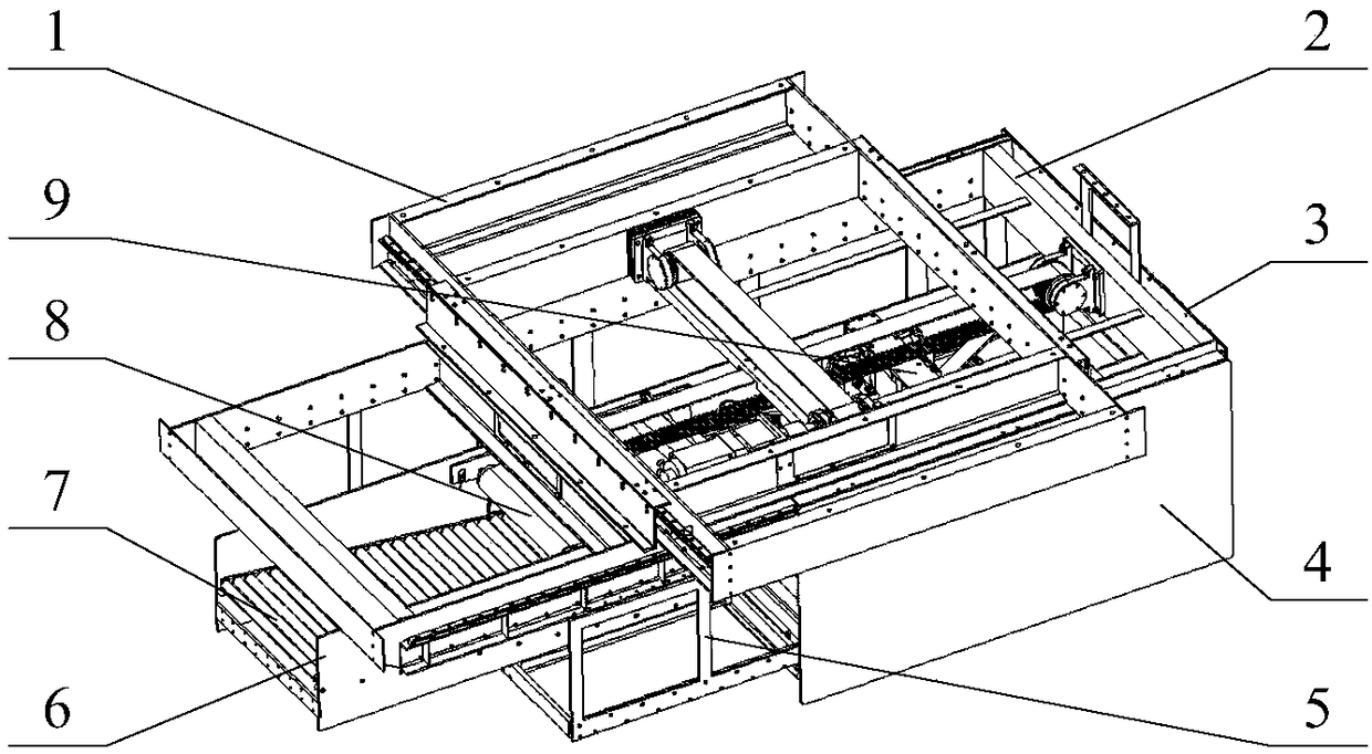
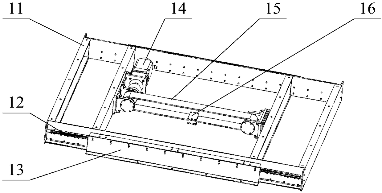
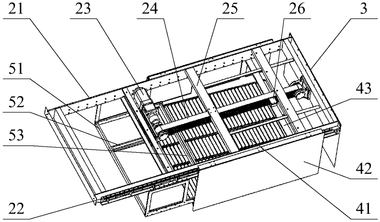

Image

  • Automatic stacking device on bagged material loading machine
  • Automatic stacking device on bagged material loading machine
  • Automatic stacking device on bagged material loading machine

Examples


Embodiment Construction

[0021] In the description of the present invention, unless otherwise specified, the orientation or positional relationship indicated by the terms "upper", "lower", "front", "rear", "left", "right", etc. are only for describing the present invention and simplifying the description, rather than Nothing indicating or implying that the referred device or structure must have a particular orientation should not be construed as limiting the invention. In addition, the terms "first", "second", etc. are used for descriptive purposes only, and should not be construed as indicating or implying relative importance. The present invention takes the front-end positioning baffle as the front end, and the bag-stopping platform as the rear end.

[0022]The following preferred embodiments of the present invention will be further described in detail in conjunction with the accompanying drawings. The following preferred modes are used to illustrate the present invention and are not intended to lim...


PUM


Abstract

The invention provides an automatic stacking device on a bagged material loading machine. The automatic stacking device comprises a bag dropping platform, a dropped bag moving mechanism and a transverse moving mechanism, wherein the bag dropping platform is used for material grouping and bag dropping; the dropped bag moving mechanism is used for moving the bag dropping platform forward and backward; the transverse moving mechanism is used for transversely moving the dropped bag moving mechanism; a front-end positioning baffle plate and a bag pushing mechanism are connected with the front and rear ends of the dropped bag moving mechanism; a middle bridge connected with the transverse moving mechanism is arranged between the bag pushing mechanism and the dropped bag moving mechanism; and a bag stopping platform, a bag conveying mechanism and a bag placing mechanism are connected onto the middle bridge. The automatic stacking device provided by the invention has the beneficial effects that through the time sequence control of the bag conveying mechanism and the bag placing mechanism, the multi-form material stacking and grouping can be achieved; through the dropped bag moving mechanism and the bag dropping platform, the material stacking, dropping and arranging can be achieved; through the transverse moving mechanism, the front-end positioning baffle plate and the bag pushing mechanism, the material stacking and positioning can be achieved; and under the precise positioning control of the transverse moving mechanism, stacking groups which are subject to a plurality of stackingcycles along the compartment width direction can be orderly spliced, and then the automatic stacking and loading requirements between any material sizes and any compartments can be met.

Description

technical field [0001] The invention relates to the field of material conveying equipment, in particular to an automatic palletizing device on a bagged material loading machine. Background technique [0002] The loading of bagged cement is done manually in most companies in my country. The existing semi-automatic loading machines still need to manually stack the bagged cement into the car. The labor intensity of the workers is still high, and the loading efficiency is difficult to improve. , and due to the harsh working environment, the inhalation of dust, etc. will cause great harm to the workers. Patent 201410424111.5 discloses a fully automatic bagged cement loading machine. The unloading device includes four unloading gates, which are two forward unloading gates and two reverse unloading gates, which realize the automatic loading of bagged cement. car, eliminating the need for manual handling. However, this loading machine can only realize the horizontal linear arrangem...

Claims


Application Information

Patent Timeline
Patent Type & Authority Applications(China)
IPC IPC(8): B65G67/04B65G57/20
CPCB65G57/20B65G67/04B65G2201/0238
Inventor 李永新王虔虔高霖王亚军宋思远郑威罗衡杨溢何林凌兴国李辉许瑞康
Owner CNBM HEFEI POWDER TECH EQUIP CO LTD
Why Eureka
Try Eureka