Mounting equipment car

A technology for installing equipment and power equipment, applied in hoisting devices, hoisting devices, transportation and packaging, etc., can solve problems affecting construction efficiency, consumption, and increasing construction costs

Inactive Publication Date: 2018-06-19
白天海
View PDF10 Cites 12 Cited by
  • Summary
  • Abstract
  • Description
  • Claims
  • Application Information

AI Technical Summary

Problems solved by technology

[0002] No similar technology has been found after searching. The installation and placement of various equipment in the current engineering construction is divided into three stages. The equipment arrives at the construction site for centralized management --- unpacking inspection, transported to the equipment foundation --- the equipment foundation is in place and corrected Installation, when the equipment is transported from the storage warehouse on the construction site for the second time, according to the appearance, weight and precision of the equipment, it is transported to the equipment foundation by means of crane, truck, forklift, etc. Inside or under the frame or pipe frame, it is difficult to lift the crane arm to directly lift the equipment to the foundation. For larger equipment transported to the foundation, generally use bracket hoists or roller bars to move the equipment to the foundation surface for alignment and installation. The process described It involves a variety of vehicles, machines and the cooperation of different professionals. The precision equipment needs special spreaders to protect the hoisting and transportation. Although the secondary transportation distance is short, it is necessary to take protective measures for the equipment in the vehicle to prevent it from falling over. Therefore, there are many links in the current equipment installation process, which will inevitably affect the construction efficiency. Safety accidents often occur, consume more materials, manpower, and vehicle resources, and increase construction costs.

Method used


Image

  • Mounting equipment car
  • Mounting equipment car
  • Mounting equipment car

Examples


Embodiment Construction

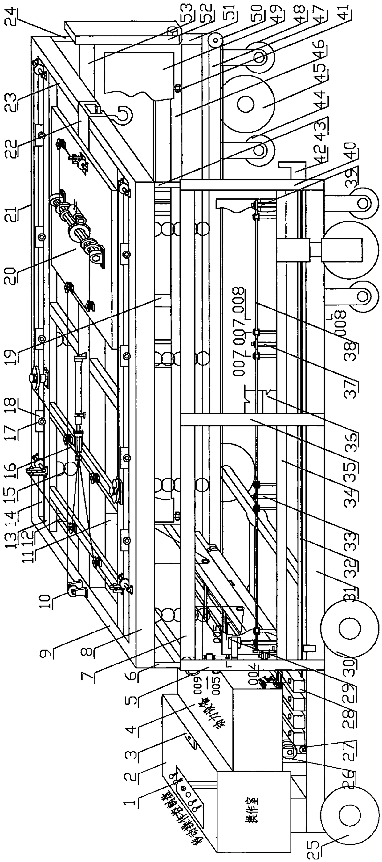
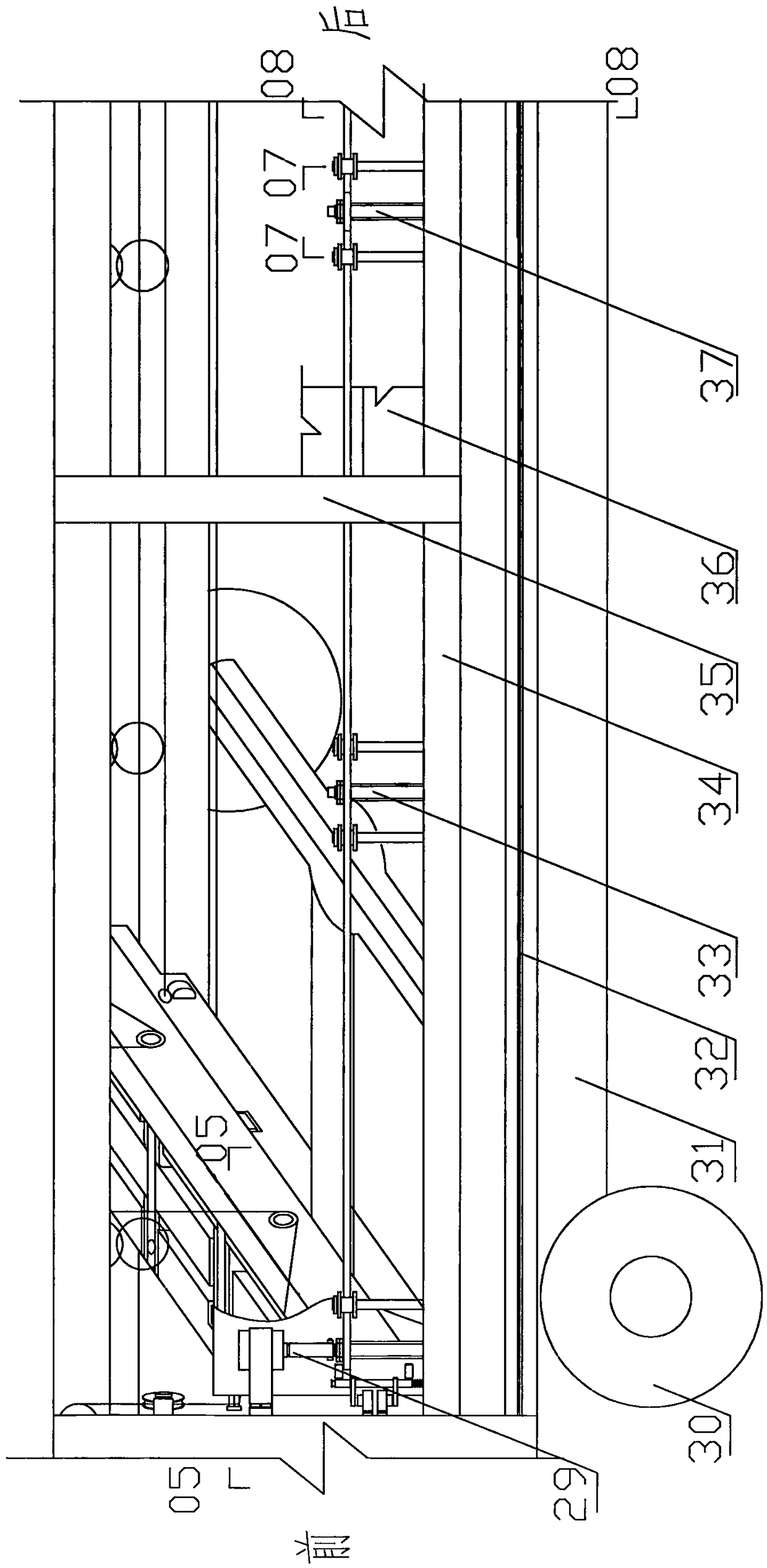
[0281] The present invention will be further described with reference to accompanying drawing, figure 1 It is a schematic diagram of the overall structure of the present invention, and its bottom beam is retracted at the bottom of the power equipment position, figure 2 for figure 1 Several bottom beams are connected to the two bottom longitudinal beams on both sides of the box by the driving mechanism. An installation equipment vehicle of the present invention is composed of power equipment, chassis, body and electrical equipment, etc., and has the basic functions of a car. Be that: box body is made of its two sides, top and bottom, and the composition of two sides structure, is connected with the left bottom longitudinal beam 31 and the lower end of right rear column 51 by left front column 5, left rear column 40, right front column 11, right rear column 51 respectively. The outer side of the right bottom longitudinal beam 47, the upper ends of the columns are respectively ...


PUM


Abstract

The invention discloses a mounting equipment car. The mounting equipment car consists of power equipment, a chassis, a car body, electric equipment and the like, and is characterized in that a first extension column 6, a second extension column 12, a third extension column 24 and a fourth extension column 43 are correspondingly mounted at the upper sections of inner cavities of stand columns at four corners of a box; the other end of each stand column is connected to the top of the box; the top of the box can be vertically lifted to lift equipment; an extension lifting crane is mounted at thetop in the box; more than one layers of cross beam support structures and drive connecting devices are mounted on the inner and outer sides of a channel between longitudinal components on the two sides of the box to form a rotary recovered movable plane support structure; the equipment can be carried on cross beams; the cross beams can be automatically recovered on the two sides of the box; and the section of the box is n-shaped. The mounting equipment car reduces the equipment mounting construction flow, removes various cranes, vehicles, forklifts and tools in traditional construction, once finishes lifting, transportation and installation on one car, achieves automatic control and precise installation, realizes mechanical equipment installation, and greatly improves the equipment mounting efficiency.

Description

technical field [0001] The invention relates to an installation equipment vehicle used for hoisting, carrying and placing equipment in place in engineering construction. Background technique [0002] No similar technology has been found after searching. The installation and placement of various equipment in the current engineering construction is divided into three stages. The equipment arrives at the construction site for centralized management --- unpacking inspection, transported to the equipment foundation --- the equipment foundation is in place and corrected Installation, when the equipment is transported from the storage warehouse on the construction site for the second time, according to the appearance, weight and precision of the equipment, it is transported to the equipment foundation by means of crane, truck, forklift, etc. Inside or under the frame or pipe frame, it is difficult to lift the crane arm to directly lift the equipment to the foundation. For larger eq...

Claims


Application Information

Patent Timeline
Patent Type & Authority Applications(China)
IPC IPC(8): B66C25/00B66C9/14B66C13/20B66C23/69B66F19/00
CPCB66C25/00B66C9/14B66C13/20B66C23/701B66F19/00
Inventor 白天海
Owner 白天海
Why Eureka
Try Eureka