
Variable-propeller system and blade zero position calibrating method

A technology of pitch control system and blade angle, which is applied in the direction of engine, engine control, wind power generation, etc. It can solve the problems of increasing the load of wind turbines, affecting the adjustment of blade angle, and not changing, so as to meet the requirements of power generation and ensure The effect of precision and simple operation steps

Inactive Publication Date: 2018-06-19
BEIJING GOLDWIND SCI & CREATION WINDPOWER EQUIP CO LTD
View PDF5 Cites 10 Cited by
  • Summary
  • Abstract
  • Description
  • Claims
  • Application Information

AI Technical Summary

Problems solved by technology

[0003] After the fan is running, if the zero position of the blade is not accurate, it will affect the actual angle adjustment of the blade. At the same time, the fault of the pitch system itself will also affect the actual angle adjustment of the blade, and there is a gap between the actual angle adjustment and the preset angle adjustment of the blade. The deviation will affect the wind speed-power curve of the unit, increase the load of the wind turbine, and affect the safe operation of the wind turbine
[0004] In order to detect the angle of the blade and facilitate the adjustment of the blade angle, an encoder is usually installed on the drive device of the pitch system to detect and assist in adjusting the blade angle. When there is a problem with the intermediate transmission mechanism of the device and the impeller, such as a failure of the reducer or an abnormality of the toothed belt, since the encoder is installed on the driving device, it can rotate normally, but the angle of the blade does not change due to the transmission failure. , in this case, the angle detected by the encoder will not match the actual angle of the blade, which will affect the operation safety of the wind turbine

Method used

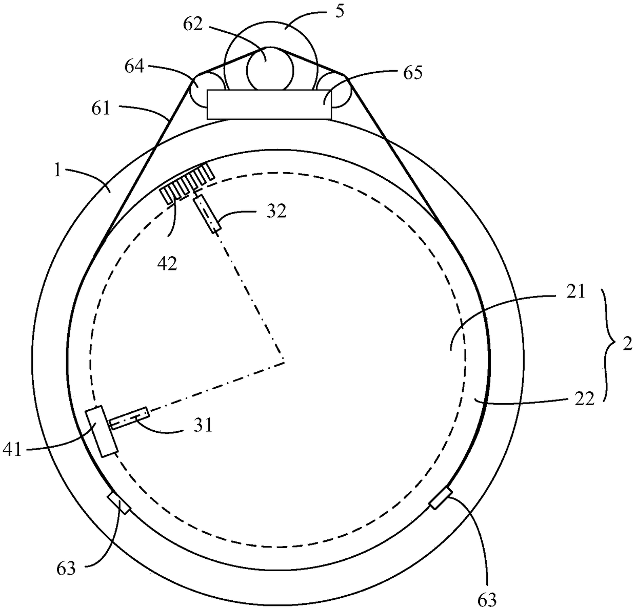
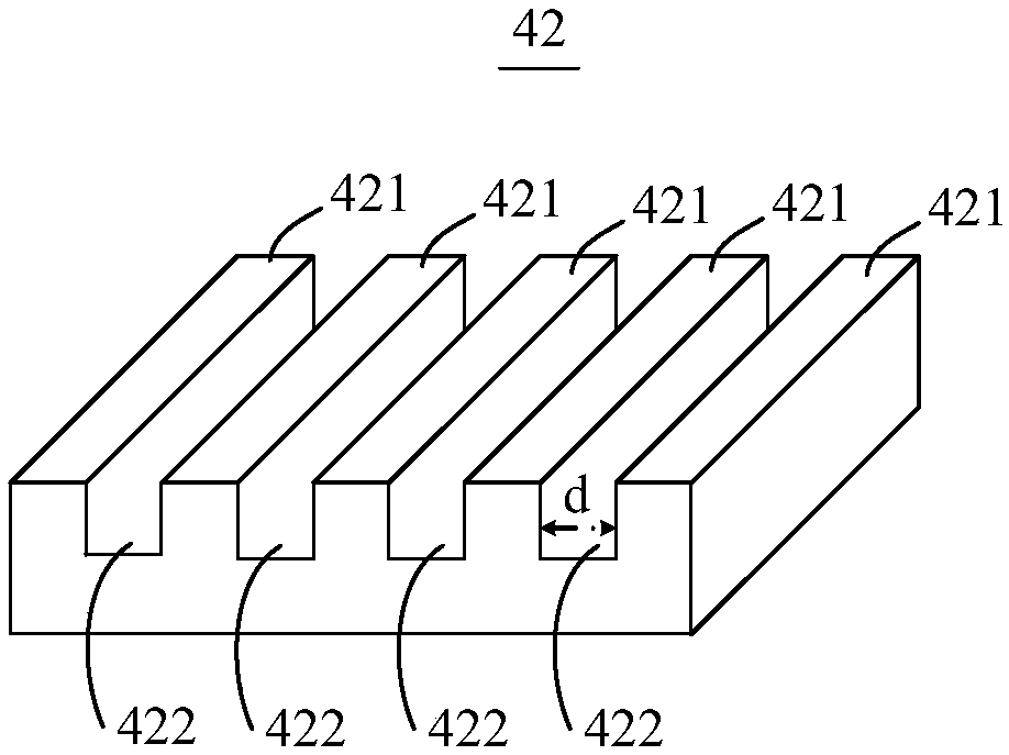
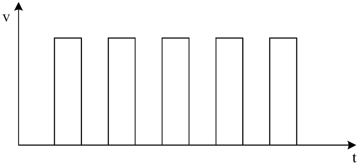

Image

  • Variable-propeller system and blade zero position calibrating method
  • Variable-propeller system and blade zero position calibrating method
  • Variable-propeller system and blade zero position calibrating method

Examples


Embodiment Construction

[0038] Embodiments of the present invention will be further described in detail below in conjunction with the accompanying drawings and examples. The detailed description and drawings of the following embodiments are used to illustrate the principles of the present invention, but not to limit the scope of the present invention, that is, the present invention is not limited to the described embodiments.

[0039]Features and exemplary embodiments of various aspects of the invention will be described in detail below. In the following detailed description, numerous specific details are set forth in order to provide a thorough understanding of the present invention. It will be apparent, however, to one skilled in the art that the present invention may be practiced without some of these specific details. The following description of the embodiments is only to provide a better understanding of the present invention by showing examples of the present invention. In the drawings and t...


PUM


Abstract

The invention relates to a variable-propeller system and a blade zero position calibrating method. The variable-propeller system comprises a variable-propeller bearing, a position detecting assembly and a trigger assembly, wherein the position detecting assembly comprises a first switch assembly for detecting whether a blade is at a first angle or not and a second switch assembly for detecting whether the blade is at a second angle or not; the trigger assembly comprises a first trigger part and a second trigger part which are arranged in the peripheral direction of a rotary ring in a spaced mode; when the trigger part and the second trigger part rotate along with the rotary ring, the first trigger part can trigger the first switch assembly and the second trigger part can trigger the secondswitch assembly; and when the first trigger part rotates to the trigger range of the first switch assembly, the second trigger part is positioned in the trigger range of the second switch assembly. The variable-propeller system can be used for checking the practical position of the blade and also can be used for calibrating the zero position of the blade, so that safe operation of a wind generating set is guaranteed.

Description

technical field [0001] The invention relates to the technical field of wind power, in particular to a pitch control system and a method for calibrating the zero-degree position of a blade. Background technique [0002] In wind turbines, the pitch system plays an important role in realizing maximum power tracking and aerodynamic braking, and its reliability is directly related to the safety of wind turbines. The pitch system can judge whether there is a fault in the wind turbine by judging whether the blade angle reaches the expected angle, so as to ensure the safe use of the blade and the stable operation of the unit. The blade angle is actually based on the zero scale position as a reference value. Therefore, the zero-degree position of the blade is very important. Before the wind turbine is running, it is necessary to align the blade angle with the physical zero-scale position of the blade, and set the blade angle to 0 degrees in the main controller. [0003] After the fa...

Claims


Application Information

Patent Timeline
IPC IPC(8): F03D7/00F03D17/00F03D13/30
CPCF03D7/00F03D13/30F03D17/00F05B2270/328Y02E10/72
Inventor 马磊李莉李庆江
Owner BEIJING GOLDWIND SCI & CREATION WINDPOWER EQUIP CO LTD
Learn More