Sanitation truck working path planning method based on road surface cleanliness detection

A technology for path planning and sanitation vehicles, applied in road cleaning, cleaning methods, vehicle position/route/height control, etc., can solve problems such as increased fuel consumption or electric energy, reduced operating efficiency, and reduced cleaning efficiency to avoid increased energy consumption. , saving water and improving the efficiency of cleaning operations

Inactive Publication Date: 2018-06-19
CHANGSHA SONNEPOWER ELECTRONICS TECH
View PDF17 Cites 14 Cited by
  • Summary
  • Abstract
  • Description
  • Claims
  • Application Information

AI Technical Summary

Problems solved by technology

[0003] (1) Due to the lack of water, the distance to the nearest water filling point is far away, and it is necessary to return to add water, resulting in a decrease in cleaning efficiency and an increase in fuel consumption or electric energy;
[0004] (2) Because the garbage bin is full, it is necessary to return to the garbage station to dump the garbage before continuing to work, resulting in a decrease in operating efficiency and an increase in fuel consumption or power;

Method used


Image

  • Sanitation truck working path planning method based on road surface cleanliness detection
  • Sanitation truck working path planning method based on road surface cleanliness detection

Examples


Embodiment 1

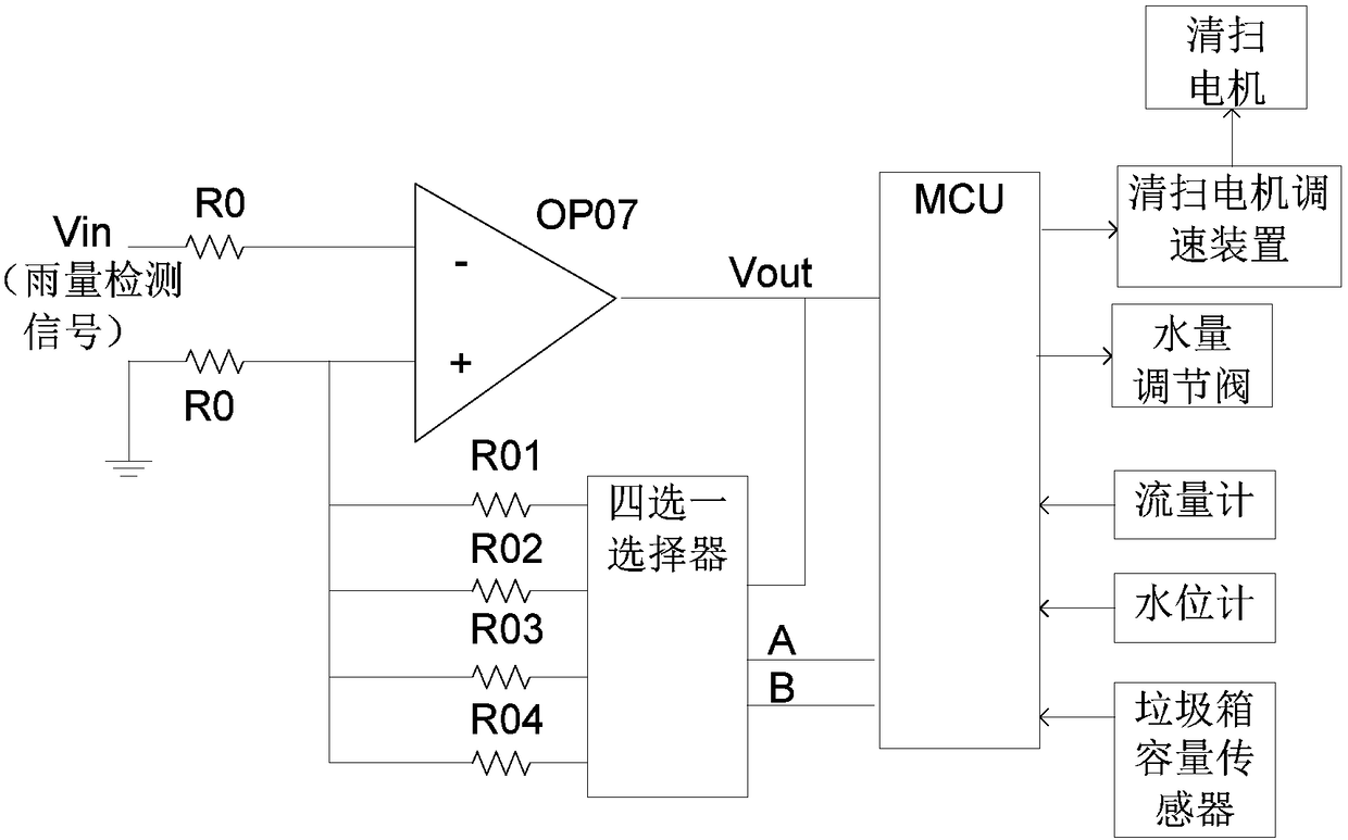
[0077] Embodiment 1: as figure 1 and 2 , a sanitation vehicle operation control method based on rainfall detection, the operation vehicle detects the real-time rainfall value during operation through the rain detection circuit based on the rainfall sensor; adjusts the opening of the water regulating valve according to the rainfall value to adjust the water spray in the cleaning mechanism amount to save water storage in the water tank.

[0078] The opening (percentage) of the water volume regulating valve K=1-k1*Rx; k1 is a constant, and the value of K is between 0-1; Rx is the output voltage value of the rain sensor. The value of k1 depends on the actual situation.

[0079] Including water replenishment control methods based on rainfall detection;

[0080] The replenishment control method comprises the steps:

[0081] Step 11: Detect parameters related to hydration:

[0082] Detect or calculate the following parameters:

[0083] (1) Detect the current remaining water sto...

Embodiment 2

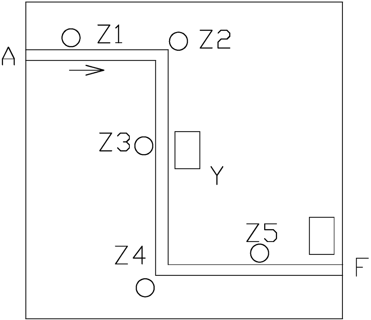
[0150] Original input information: water tank level (a), collected garbage volume (b), current vehicle location information (X), current vehicle speed (c), elapsed operating time (t), elapsed operating mileage (k), designated garbage dumping Point location information (Y), designated water point location information 1 (Z1), designated water point location information 2 (Z2), and job end point location information (F).

[0151] Water tank capacity: L; Garbage box capacity: M

[0152] Data information calculated from raw input information:

[0153] Current remaining water storage = a*ε;

[0154] The current remaining garbage bin capacity = M-b;

[0155] The average amount of water sprinkled per unit time of work β1=(L-a*ε) / t;

[0156] The average amount of water sprinkled per unit of kilometers that has been operated β2=(L-a*ε) / k;

[0157] The average amount of garbage collected per unit time of work γ1=b / t;

[0158] The average amount of garbage collected per unit of kilom...


PUM


Abstract

The invention discloses a sanitation truck working path planning method based on road surface cleanliness detection. The road surface cleanliness is determined by the following methods. A method 1 comprises calculating the increment of garbage in a garbage bin per unit time to determine road cleanliness. A method 2 comprises that a driver determines the road cleanliness based on vision. A method 3comprises that a camera is installed on the front end of the sanitation truck to obtain a cleaning site road image and send the cleaning site road image to a remote monitoring platform; an operator of the remote monitoring platform determines the road cleanliness based on the cleaning site road image obtained by the camera; and the speed of a cleaning motor is controlled based on the cleanlinessof the road. The sanitation truck working path planning method further includes a garbage dumping control method. The sanitation truck working path planning method based on road surface cleanliness detection is easy to implement, and can realize intelligent watering and garbage dumping.

Description

technical field [0001] The invention relates to a sanitation vehicle operation path planning method based on road surface cleanliness detection. Background technique [0002] Existing sanitation vehicles responsible for cleaning the road, on their travel route, when to add water and when to dump garbage, all need to be manually determined, which often leads to the following problems: [0003] (1) Due to the lack of water, the distance to the nearest water filling point is far away, and it is necessary to return to add water, resulting in a decrease in cleaning efficiency and an increase in fuel consumption or electric energy; [0004] (2) Because the garbage bin is full, it is necessary to return to the garbage station to dump the garbage before continuing to work, resulting in a decrease in operating efficiency and an increase in fuel consumption or power; [0005] Therefore, it is necessary to design a new path planning method for sanitation vehicles based on road cleanli...

Claims


Application Information

Patent Timeline
Patent Type & Authority Applications(China)
IPC IPC(8): G05D1/02G01W1/14G05D27/02E01H1/00
CPCE01H1/00G01W1/14G05D1/021G05D1/0293G05D27/02
Inventor 罗轶峰郭彦蕊张少华张涛刘占军
Owner CHANGSHA SONNEPOWER ELECTRONICS TECH
Why Eureka
Try Eureka