Eureka AIR delivers breakthrough ideas for toughest innovation challenges, trusted by R&D personnel around the world.

Novel valve controlled sealing lead acid storage battery activated charge-discharge device and novel valve controlled sealing lead acid storage battery activated charge-discharge method

A technology of lead-acid batteries and batteries, which is applied in battery circuit devices, charging and maintenance charging/discharging, circuit devices, etc., and can solve problems such as early battery failure, high battery maintenance costs, and unsatisfactory maintenance effects

Inactive Publication Date: 2018-06-19
STATE GRID ANHUI ELECTRIC POWER CO LTD ANQING POWER SUPPLY CO +2
View PDF7 Cites 0 Cited by
  • Summary
  • Abstract
  • Description
  • Claims
  • Application Information

AI Technical Summary

Problems solved by technology

However, due to the quality defects of the VRLA battery itself, as well as improper use, the battery will fail early, and it will be oversaturated or undercharged for a long time during use, which will lead to a decrease in battery capacity and reduce its service life.
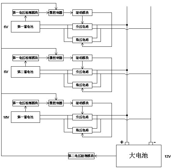
Faced with the problems of high battery maintenance cost and unsatisfactory maintenance effect, in order to ensure the service life of the battery and the reliable operation of the power system, the traditional battery maintenance methods and means based on ordinary discharge operations have not been able to maintain the battery and extend the life of the battery. Therefore, this patent proposes a new valve-controlled sealed lead-acid battery activation charging and discharging unit, which can make up for the shortcomings of traditional maintenance methods, and realize multiple charging and discharging operations by adding a buck-boost circuit during the charging and discharging process of the battery, thereby improving Increase the capacity of the battery and prolong its service life

Method used


Image

  • Novel valve controlled sealing lead acid storage battery activated charge-discharge device and novel valve controlled sealing lead acid storage battery activated charge-discharge method

Examples


Embodiment Construction

[0014] Such as figure 1 As shown, a novel valve-controlled sealed lead-acid battery activation charging and discharging device includes a first storage battery, a second storage battery, a third storage battery and a large battery, and the first storage battery, the second storage battery and the third storage battery are respectively connected to the The large battery is connected, and a boost circuit and a step-down circuit are provided on the wire, and the boost circuit and the step-down circuit are connected in parallel; the first storage battery, the second storage battery and the third storage battery are connected with the voltage detection module, the microcontroller and the drive The modules are connected, the drive module is connected with the boost circuit and the step-down circuit, and the drive module is used to drive the boost circuit and the step-down circuit; the large battery is connected with the second voltage detection module, and the second voltage detectio...


PUM


Abstract

A novel valve controlled sealing lead acid storage battery activated charge-discharge device comprises a first storage battery, a second storage battery, a third storage battery and a large battery. The first to third storage batteries are connected with the large battery separately via the conducting wires, a boost circuit and a buck circuit are arranged on the conducting wires and are connectedin parallel, and the first to third storage batteries are connected with the voltage detection modules, a microcontroller and a driving module orderly. The driving module is connected with the boost circuit and the buck circuit and is used to drive the boost circuit and the buck circuit, the large battery is connected with the second voltage detection modules, and the second voltage detection modules are connected with the microcontroller separately. By adding the boost and buck circuits during the charge and discharge process of the storage batteries to realize the repeated charge and discharge operations, the novel valve controlled sealing lead acid storage battery activated charge-discharge device and the novel valve controlled sealing lead acid storage battery activated charge-discharge method provided by the present invention enable the capacity of the batteries to be improved and the service lives to be prolonged.

Description

technical field [0001] The invention relates to the field of activation of lead-acid batteries, in particular to a novel valve-controlled sealed lead-acid battery activation charging and discharging device and method thereof. Background technique [0002] With the development of my country's information, technology and automation industries, the safe and reliable operation of power supply systems is facing huge challenges. Electric power and other industries have also put forward stricter requirements for the uninterrupted power supply of the power system. As a representative of "maintenance-free" batteries, Valve Regulated Lead Acid (VRLA) batteries have been widely used. However, due to the quality defects of the VRLA battery itself, as well as improper use, the battery will fail early, and it will be in a state of oversaturated charging or long-term power loss during use, which will lead to a decrease in battery capacity and shorten its service life. Faced with the prob...

Claims


Application Information

Patent Timeline
IPC IPC(8): H02J7/00
CPCH02J7/0069H02J7/342
Inventor 李友平毛峰浦劲松钟成元唐怀东赵慧娟徐立群王彪吕洋程江洲
Owner STATE GRID ANHUI ELECTRIC POWER CO LTD ANQING POWER SUPPLY CO
Why Eureka
Eureka Blog
Learn More