
Automatic switching circuit for main power source and backup power source

A backup power supply, automatic switching technology, applied in the field of electronics, can solve problems such as complex circuit structure

Inactive Publication Date: 2018-06-19
SHANGHAI BEILING
View PDF4 Cites 5 Cited by
  • Summary
  • Abstract
  • Description
  • Claims
  • Application Information

AI Technical Summary

Problems solved by technology

[0005] The technical problem to be solved by the present invention is to overcome the defect of complex circuit structure when the high-voltage backup power is switched to the low-voltage main power in the power switching mode based on MOS switches in the prior art, and to provide a kind of main power and backup power that can Automatic switching circuit of main power supply and standby power supply with simple circuit structure, reliable circuit and low cost

Method used


Image

  • Automatic switching circuit for main power source and backup power source

Examples


Embodiment Construction

[0045] The present invention is further illustrated below by means of examples, but the present invention is not limited to the scope of the examples.

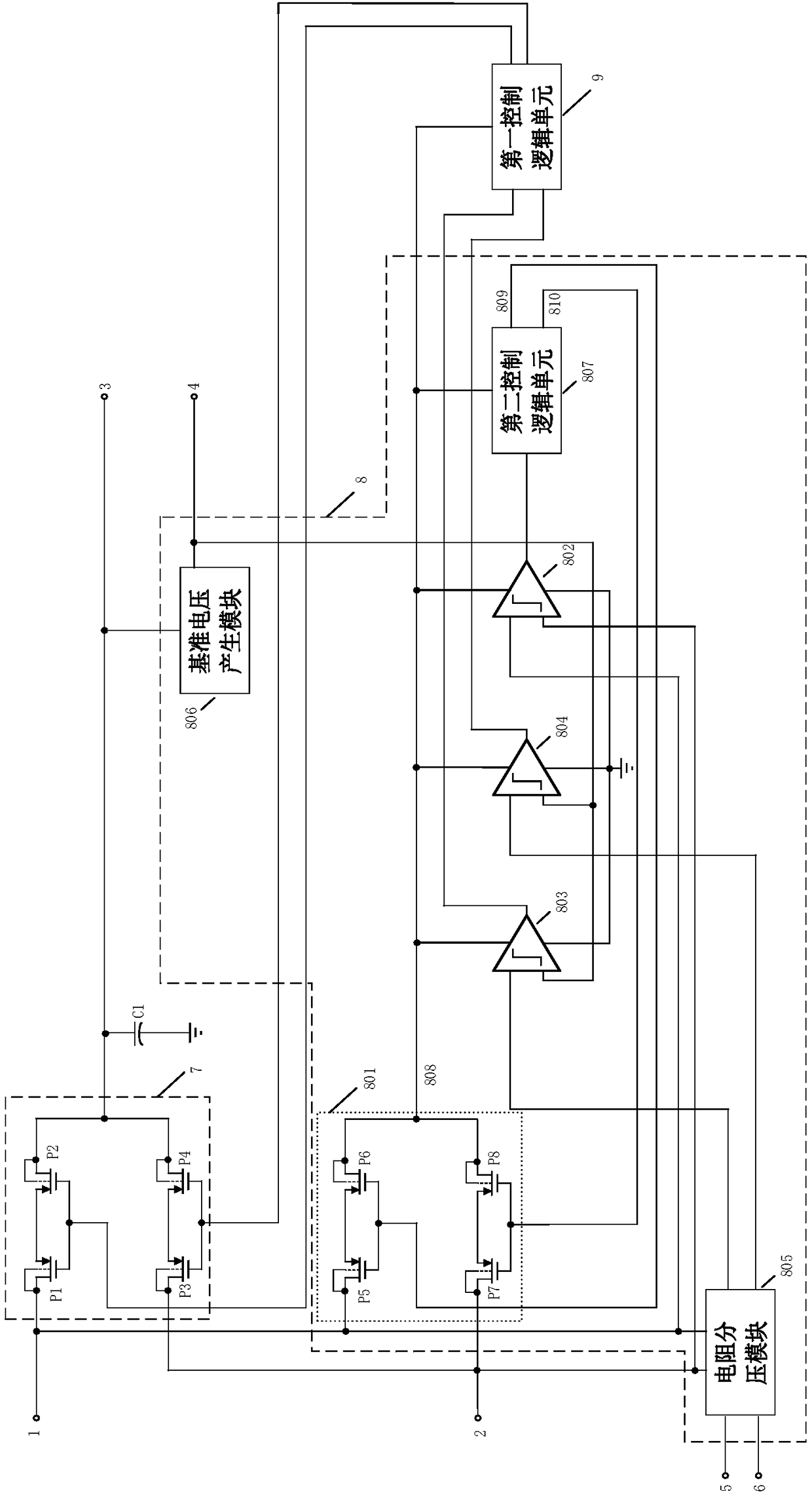
[0046] Such as figure 1 As shown, the automatic switching circuit between the main power supply 1 and the backup power supply 2 provided in this embodiment includes a power output terminal 3 , a PMOS power switch 7 , a first control logic unit 9 and a power monitoring module 8 . The PMOS power switch 7 is connected to the main power supply 1 and the standby power supply 2 . A voltage stabilizing capacitor C1 is connected in series between the power supply output terminal 3 and the ground, and the voltage stabilizing capacitor can stabilize the voltage output by the power supply output terminal 3 when the power supply is switched, avoiding the jitter of the voltage, and ensuring a smooth transition of the output power supply when the power supply is switched .

[0047] The PMOS power switch 7 includes a first PMOS transistor ...


PUM


Abstract

The invention discloses an automatic switching circuit for a main power source and a backup power source. The automatic switching circuit is composed of a power output terminal, a PMOS power source change-over switch, a first control logic unit and a power monitoring module. The power monitoring module determines whether a main power source meets a power supply requirement; if so, a main power source supply enabling signal is outputted to a first control logic unit; if not, whether a backup power source meets a power supply requirement is determined; and if so, a backup power source function enabling signal is outputted to the first control logic unit. The first control logic unit controls the main power source to output power to a power output terminal after receiving the main power source supply enabling signal and controls the backup power source to output power to the power output after receiving the backup power source supply enabling signal. The power monitoring module is used for comparing voltages of the main power source and the backup power source to select one power source with the higher voltage to provide power for the first control logic unit. Therefore, switching from the backup power source with the higher voltage to the main power source with the lower voltage is realized automatically. Moreover, the circuit is simple; the reliability is high; and the cost is low.

Description

technical field [0001] The invention belongs to the field of electronic technology, and in particular relates to an automatic switching circuit for a main power supply and a backup power supply. Background technique [0002] With the development of electronic technology, various industries have higher and higher requirements for power supply reliability. Many important application scenarios require uninterrupted power supply. Most uninterruptible power supply systems are composed of a main power supply and a backup power supply. Generally, the main power supply is Direct current, backup power source is battery. After the main power supply is lost, the electronic equipment can still operate normally under the backup battery power supply. The switching technology between the main power supply and the backup power supply is widely used in dual power supply application scenarios. [0003] The traditional power switching scheme uses the single-phase conduction characteristic of...

Claims


Application Information

Patent Timeline
IPC IPC(8): H02J9/06
CPCH02J9/06H02J9/068Y02B70/30Y04S20/20
Inventor 李鹏石飞张煜彬袁文师陈宁罗赛
Owner SHANGHAI BEILING
Learn More