Low-inertia rotor of permanent magnet motor

A permanent magnet motor and rotor technology, applied in the field of low inertia rotors, can solve the problems of reducing the effective utilization rate of the rotor core, affecting the performance of the permanent magnet motor, and discounting the effective length of the rotor core, so as to improve the effective utilization rate, Ensure the effect of effective length and small material consumption

Pending Publication Date: 2018-06-19
NINGBO ANXIN CNC TECH
View PDF12 Cites 1 Cited by
  • Summary
  • Abstract
  • Description
  • Claims
  • Application Information

AI Technical Summary

Problems solved by technology

After the rotor core module is made, since the rivet head and the rivet head of the rivet used are higher than the end plane of the rotor core module, the rivet head or the rivet head of the rivet will be against each other when the rotor core modules are stacked , resulting in gaps between adjacent rotor core modules, the gaps are often lined with the spacer rings, but this reduces the effective length of the rotor core in the case of the same rotor length (because the spacer rings The part of the permeable magnetic circuit that does not participate in the electromagnetic reaction), reduces the effective utilization of the rotor core, and even affects the performance of the permanent magnet motor

Method used


Image

  • Low-inertia rotor of permanent magnet motor
  • Low-inertia rotor of permanent magnet motor
  • Low-inertia rotor of permanent magnet motor

Examples


Embodiment Construction

[0016] The present invention will be further described in detail below in conjunction with the accompanying drawings and embodiments.

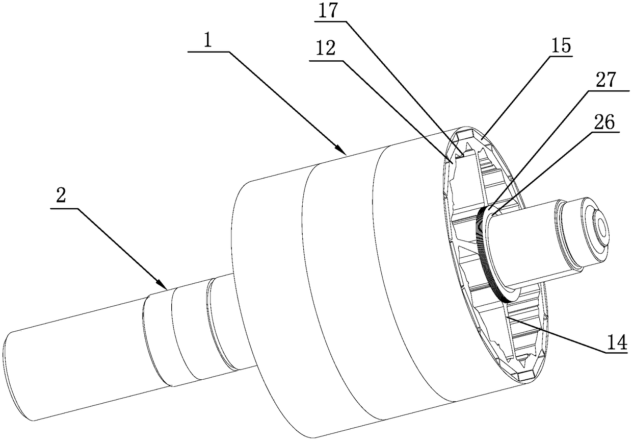
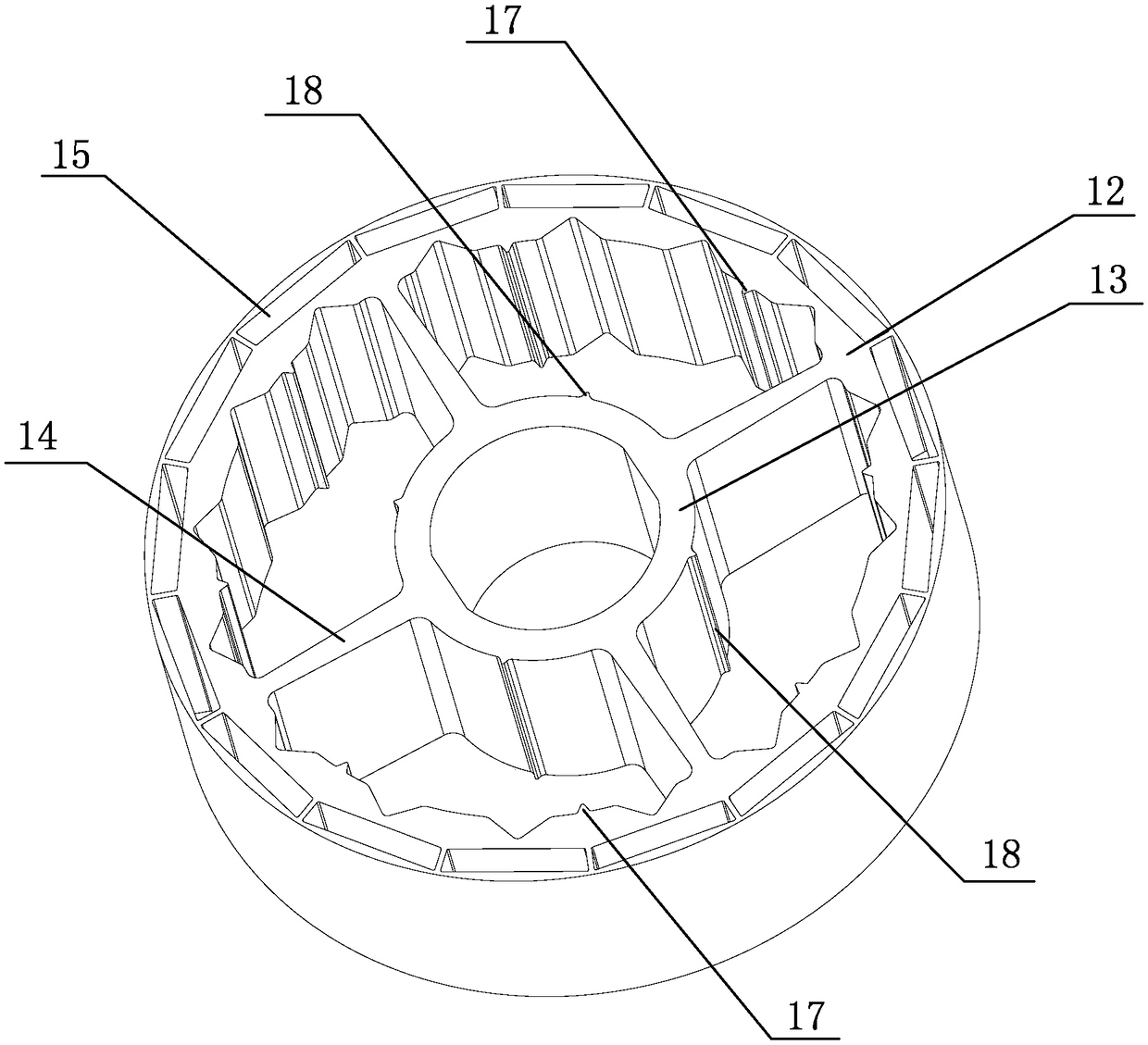
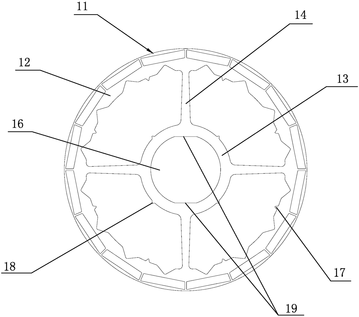
[0017] A low-inertia rotor of a permanent magnet motor proposed by the present invention, as shown in the figure, consists of three rotor core modules 1 connected in series on the rotating shaft 2 and press-fitted together with the rotating shaft 2. The rotor core module 1 consists of multiple Two rotor punches 11 are stacked and welded; the rotor punch 11 includes an outer ring 12, an inner ring 13, and four radial spokes 14 radially connecting the outer ring 12 and the inner ring 13, and the outer ring 12 is close to its outer circumference. There are 16 magnetic steel grooves 15 for embedded magnetic steel (not shown in the figure) evenly arranged along the circumferential direction at the position. The magnetic steel grooves 15 are embedded with magnetic steel. The inner ring 13 has a central inner hole 16. Eight inner peripheral welding p...


PUM


Abstract

The invention discloses a low-inertia rotor of a permanent magnet motor, and the rotor is formed in a way that a plurality of rotor core modules are connected in series to a rotating shaft and are compressed together with the rotating shaft. Each iron core module is formed by the stacked welding of a plurality of rotor punching sheets. The rotor is advantageous in that the plurality of rotor punching sheets form one iron core module, which means that the plurality of rotor punching sheets forming one iron core module are welded together, but not riveted together through rivets, thereby avoiding a condition that the head of a rivet or a rivet connector is higher than an end plane of the rotor core module during the riveting. Therefore, the plurality of rotor core modules can be closely attached without gaps after stacking, thereby guaranteeing the effective length of the rotor core, improving the effective utilization rate of the rotor core, and improving the performances of the permanent magnet motor. Meanwhile, the rotor saves lining spacer rings between the adjacent iron core modules, and reduces the cost.

Description

technical field [0001] The invention relates to a motor rotor structure, in particular to a low-inertia rotor of a permanent magnet motor. Background technique [0002] As we all know, the rotor of the motor needs the rotor core and the shaft without exception, and the rotor of the permanent magnet motor also contains magnetic steel. Different permanent magnet motors will have different rotor structures because of their different requirements for the magnetic conduction magnetic circuit. [0003] For permanent magnet motors with built-in magnetic steel, most of the rotor cores adopt the rotor punching laminated structure, and the rotor punching laminated structure is riveted with rivets, and the rotor punching laminated is nothing more than a whole rotor core , or made into a rotor core module, and then several rotor core modules are stacked to form a rotor core. After the rotor core module is made, because the rivet head and the rivet head of the rivet used are higher than...

Claims


Application Information

Patent Timeline
Patent Type & Authority Applications(China)
IPC IPC(8): H02K1/27
CPCH02K1/276
Inventor 王必生金阳洋张波褚先章林井福李爽蒋勤
Owner NINGBO ANXIN CNC TECH
Why Eureka
Try Eureka