Hobbing machine deburring device
A deburring and gear hobbing machine technology, which is applied to gear tooth manufacturing devices, gear cutting machines, gear teeth, etc., can solve the problems of time-consuming and laborious, easy hand injury when installing workpieces, and easy hand injury when disassembling workpieces, so as to improve work efficiency and save manpower , the effect of improving practicality
Active Publication Date: 2019-05-03
CHONGQING SHUNHUAI MACHINERY MFG CO LTD
View PDF6 Cites 0 Cited by
- Summary
- Abstract
- Description
- Claims
- Application Information
AI Technical Summary
Problems solved by technology
[0003] In the existing hobbing machine for processing straight teeth, after the gear hobbing is completed by the gear hobbing machine, there are usually burrs or sharp corners on the gear edge. It is easy to injure hands when disassembling the workpiece, and when the workpiece is sorted in the next process, it is also easy for workers to injure hands when loading the workpiece
Method used
View moreImage
Smart ImageViewing Examples

Examples
Embodiment Construction
[0018] The present invention will be described in further detail below by means of specific embodiments:
Login to View More PUM
 Abstract
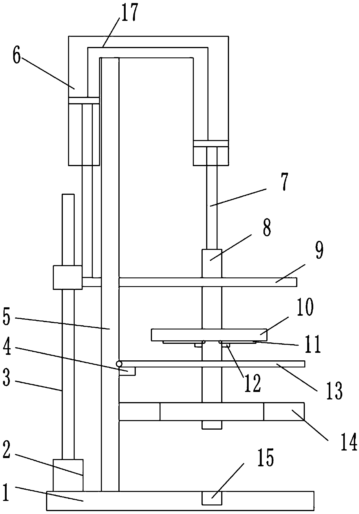
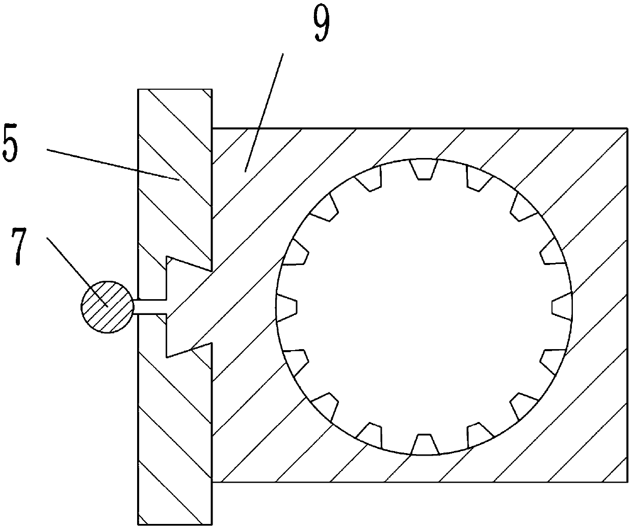
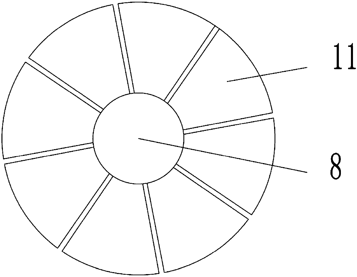
The invention belongs to the technical field of gear machining, and particularly discloses a gear hobbing machine deburring device comprising a base. A central shaft is arranged on the base, a gear positioning table is arranged above the base, and a through hole is formed in the gear positioning table. The central shaft penetrates through the through hole, and a plurality of movable supporting blades are hinged to the central shaft; one movable supporting blade is provided with a positioning block, and fixed supporting blocks are arranged below the movable supporting blades. The portion, abovethe movable supporting blades, of the central shaft is an inflatable shaft, and a magnet is arranged at the upper end of the inflatable shaft. A vertical support is arranged on the base. The verticalsupport is provided with a deburring disc provided with an inner hole matched with the contour of a gear, and a deburring sand layer is arranged on the surface of the inner hole. The upper end of thevertical support is provided with a U-shaped cylinder body, and the U-shaped cylinder body is provided with a first piston and a second piston. A first piston rod is connected with a lifting drivingmechanism, the second piston is located above the deburring disc, and an electromagnet is arranged at the lower end of a second piston rod. According to the scheme, the deburring process of the gear after gear hobbing machining of a gear hobbing machine is realized.
Description
technical field [0001] The invention belongs to the technical field of gear processing, in particular to a deburring device for a gear hobbing machine. Background technique [0002] The gear hobbing machine is a traditional equipment for manufacturing gears. The gear blank is installed on the gear hobbing machine for processing. It can cut straight and helical cylindrical gears, and can also process worm gears and sprockets. With the rapid process of industrialization, more and more special equipment is applied to various fields. The hobbing machine is divided into a hobbing machine for straight teeth and a hobbing machine for helical cylindrical gears; thus greatly improving production efficiency and processing quality. . [0003] In the existing hobbing machine for processing straight teeth, after the gear hobbing is completed by the gear hobbing machine, there are usually burrs or sharp corners on the gear edge. It is easy to injure hands when disassembling workpieces, ...
Claims
Login to View More Application Information
Patent Timeline
 Patent Type & Authority Patents(China)
IPC IPC(8): B23F19/00B23F23/06
CPCB23F19/00B23F23/06
Inventor 刘险峰
Owner CHONGQING SHUNHUAI MACHINERY MFG CO LTD
Features
- R&D
- Intellectual Property
- Life Sciences
- Materials
- Tech Scout
- Unparalleled Data Quality
- Higher Quality Content
- 60% Fewer Hallucinations
Learn More Browse by: Latest US Patents, China's latest patents, Technical Efficacy Thesaurus, Application Domain, Technology Topic, Popular Technical Reports.
© 2025 PatSnap. All rights reserved.Legal|Privacy policy|Modern Slavery Act Transparency Statement|Sitemap|About US| Contact US: help@patsnap.com