Slender hole deburring method based on tip-effect-induced pyrite reaction

A cutting-edge effect, slender hole technology, applied in the field of machining, can solve the problems of complex process, incomplete removal, difficult burr removal, etc., to achieve the effect of thorough burr removal, strong adaptability and high efficiency

Active Publication Date: 2018-06-22
JIANGSU UNIV
View PDF6 Cites 0 Cited by
  • Summary
  • Abstract
  • Description
  • Claims
  • Application Information

AI Technical Summary

Problems solved by technology

[0005] The purpose of the present invention is to solve the difficulty in removing the burr in the elongated hole, and the existing deburring methods have problems such as complex process and incomplete removal in varying degrees, and to invent a method for removing the burr in the elongated hole based on the tip effect that induces sulfur-iron reaction. method

Method used


Image

  • Slender hole deburring method based on tip-effect-induced pyrite reaction
  • Slender hole deburring method based on tip-effect-induced pyrite reaction
  • Slender hole deburring method based on tip-effect-induced pyrite reaction

Examples


Embodiment 1

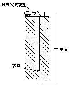
[0028] like figure 1 .

[0029] A kind of slender blind hole deburring method based on tip effect induced sulfur-iron reaction, it comprises the following steps:

[0030] The first step is to pour sulfur powder into the bottom of the elongated blind hole, and the amount of addition is appropriate to cover the burr area; the purity of the sulfur powder used is preferably above 99.99%; the elongated hole that needs to be cleaned of burrs should be vertical location, the same below;

[0031] The second step is to install the waste gas collection device on the slender orifice; the waste gas collection device can use an inverted conical glass cover, and the glass cover is connected with a balloon or an air bag with a built-in 10% concentration of sodium hydroxide absorption solution to collect the generated during the reaction. Exhaust gas and purification;

[0032] The third step is to energize the parts as a whole, and the energization voltage is DC 24-48V. Using the character...

Embodiment 2

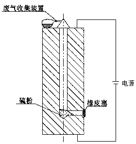
[0035] like figure 2 shown.

[0036] A method for deburring elongated vertically and horizontally through holes based on tip effect induced sulfur-iron reaction, which comprises the following steps:

[0037] The first step is to block the horizontal hole with a stopper (such as a rubber stopper or other non-chemically reactive soft plug) to prevent the sulfur powder from running out of the horizontal hole during the reaction, and then pour the sulfur powder into the elongated horizontal hole In the vertical hole, it is advisable to add the amount to cover the burr area; the purity of the sulfur powder used should preferably be above 99.99%

[0038] The second step is to install the waste gas collection device on the slender orifice; the waste gas collection device can use an inverted conical glass cover, and the glass cover is connected with a balloon or an air bag with a built-in 10% concentration of sodium hydroxide absorption solution to collect the generated during the r...

Embodiment 3

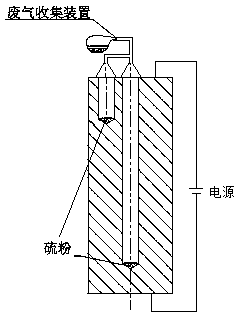
[0042] like image 3 .

[0043] A method for deburring two or more elongated blind holes based on tip effect induced sulfur-iron reaction, which comprises the following steps:

[0044] In the first step, pour the sulfur powder into the bottom of two or more elongated blind holes respectively, and the amount of addition is appropriate to cover the burr area; the purity of the sulfur powder used should preferably be above 99.99%; the burr needs to be cleaned in specific cases. The slender holes should be in a vertical position, or partly vertical, partly inclined; the horizontal slender blind holes should be divided into sections, after cleaning the vertical blind holes, turn them 90 degrees to make them vertical, and then repeat steps 1 to 4;

[0045] The second step is to install an exhaust gas collection device at the slender orifice; the exhaust gas collection device can use an inverted conical glass cover, and then use a balloon or air bag with a built-in 10% concentration...


PUM


Abstract

Provided is a slender hole deburring method based on tip-effect-induced pyrite reaction. The slender hole deburring method includes the steps that elemental sulfur is firstly poured into the bottom ofa slender hole, then an exhaust gas collecting device is installed on the slender hole, then a whole part is energized, and the characteristics of minimum sectional area of burrs and maximum value ofresistance are used for increasing the temperature of the burrs and inducing the pyrite reaction, so that the burr in the slender hole can be removed. According to the slender hole deburring method,burrs of complex structural parts such as a complex cavity, a penetrating and crossing hole system, a deep hole, and a blind hole has high adaptivity, and the burrs of different positions of parts canbe removed at the same time, not only the burrs are removed completely but also the efficiency is high.

Description

technical field [0001] The invention belongs to the technical field of mechanical processing, and relates to a method for deburring elongated holes, in particular to a method for deburring elongated holes based on tip effect-induced sulfur-iron reaction. Background technique [0002] In the metal cutting process, various processing methods will produce burrs to varying degrees, which often appear on the joints or edges of two surfaces, and generally appear as tiny sharp protrusions. The existence of burrs seriously affects the quality and precision of parts or products. Taking the elongated hole as an example, it is mostly used as the flow channel of the working medium in hydraulic or pneumatic components. Once the burrs fall off during use, once they enter the circuit of the hydraulic or pneumatic system, not only will the moving parts be stuck, the circuit or filter screen will be blocked, causing accidents, but it will also cause fluid turbulence or non-laminar flow, red...

Claims


Application Information

Patent Timeline
Patent Type & Authority Applications(China)
IPC IPC(8): B23H9/02B23H3/00B23H11/00
CPCB23H3/00B23H9/02B23H11/00
Inventor 胥保文王宏宇许增张祥李乐
Owner JIANGSU UNIV
Why Eureka
Try Eureka