Injection mold for easy cooling

An injection mold and cooling pipe technology, applied in the field of injection molds that facilitate cooling, can solve the problems of increasing the tightness of the mold plastic to the rubber product, prolonging the product molding cycle, and product strain and deformation.

Active Publication Date: 2020-10-27
CHONGQING YINSHENG MOLD
View PDF4 Cites 0 Cited by
  • Summary
  • Abstract
  • Description
  • Claims
  • Application Information

AI Technical Summary

Problems solved by technology

Since the plastic product cannot completely adhere to the side of the lower mold during the process of removing the upper mold, some parts adhere to the upper mold, causing the product to be strained and deformed
The current solution is to extend the cooling time of the product and increase the tightness of the mold plastic to the rubber product. This method prolongs the molding cycle of the product and reduces the production efficiency of the product.

Method used


Image

  • Injection mold for easy cooling
  • Injection mold for easy cooling

Examples


Embodiment 2

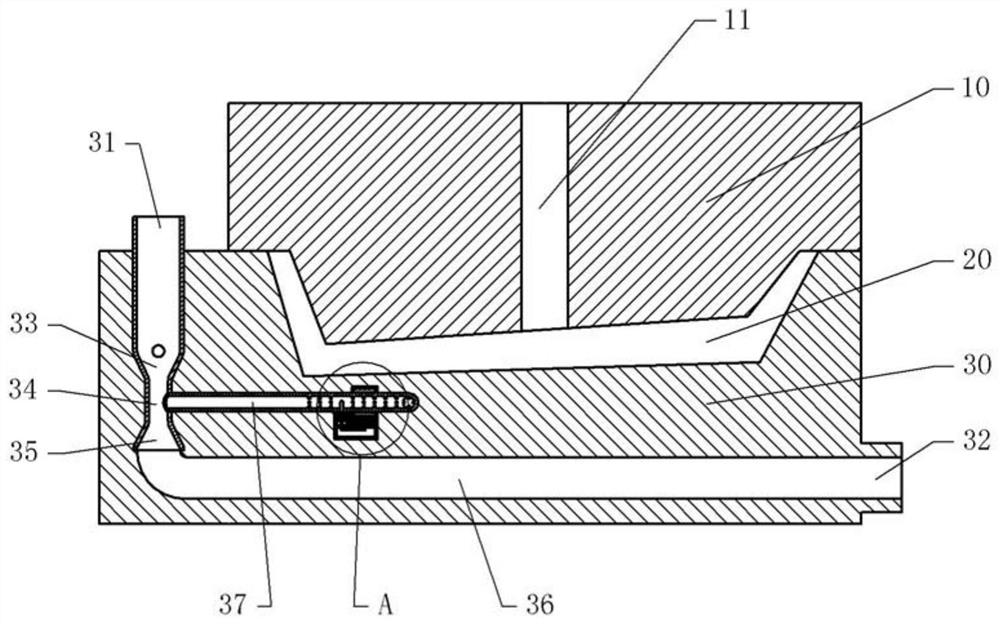
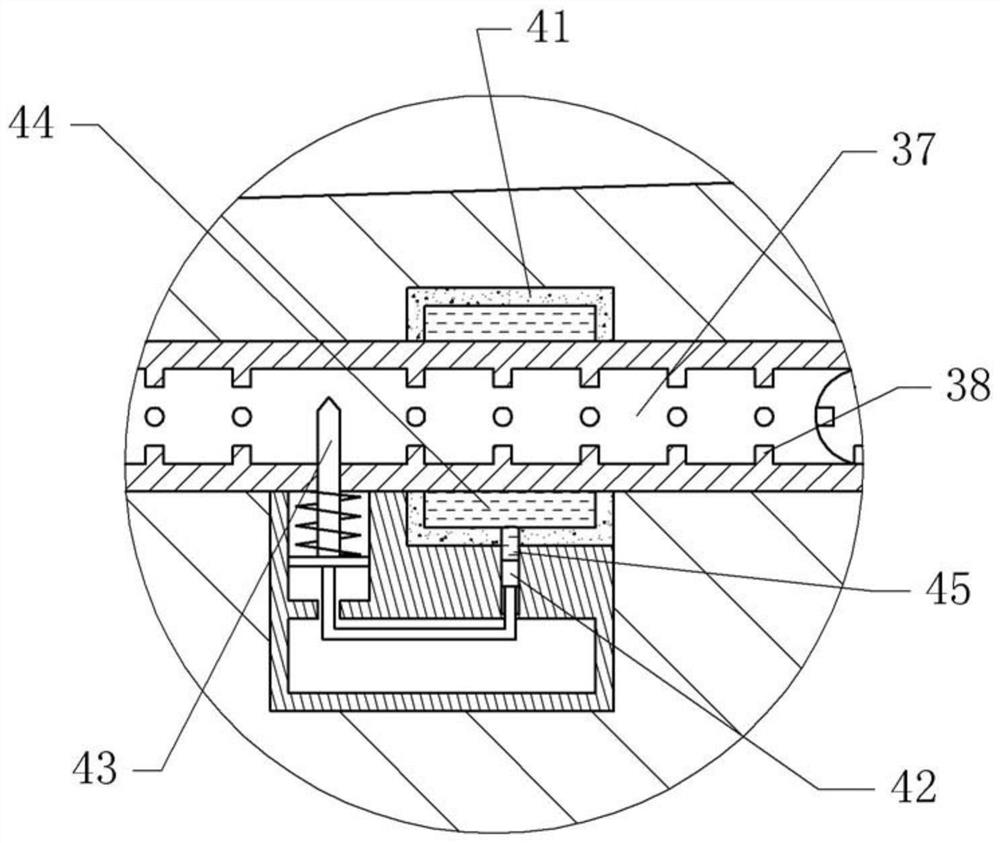
[0030] The difference between embodiment two and embodiment one is that in embodiment two, the throttling device includes a temperature sensor, a solenoid valve and a controller, the temperature sensor and the solenoid valve are all electrically connected to the controller, and the temperature sensor extends into the capillary cooling tube, The spool of the solenoid valve extends into the capillary cooling tube. The temperature sensor can monitor the temperature in the capillary cooling tube in real time, and send a feedback signal to the control gas. At the same time, the controller will send an execution signal to the solenoid valve, so that the depth of the solenoid valve into the capillary cooling tube can be changed, thereby changing the cooling water in the capillary cooling tube. traffic.


PUM


Abstract

The invention relates to the field of plastic injection molding, and particularly discloses an injection mold capable of easily cooling. The injection mold comprises an upper die and a lower die, theupper die and the lower die are internally provided with a cooling water channel and a plurality of capillary cooling tubes which are around a die cavity, and the capillary cooling tubes are disposedbetween the cooling water channel and the die cavity; a water inlet communicates with a water pump through a liquid inlet pipe, and the liquid inlet pipe includes an inlet section, a pore throat and adiffusion section; the inlet section communicates with the water pump, and the diffusion section communicates with the cooling water channel; one ends of the capillary cooling tubes communicate withthe inlet section, and the other ends of the capillary cooling tubes communicate with the pore throat; a throttling device is arranged at the periphery of each of the capillary cooling tubes, and thethrottling device comprises an expansion chamber surrounding the periphery of each of the capillary cooling tubes, a slide rail communicating with the expansion chamber, and a needle valve for throttling the capillary cooling tubes; and a piston is arranged in the slide rail, the piston is connected with a valve element of the needle valve, and the expansion chamber is filled with a thermal-expansion substance. During the injection molding, the temperature in a high-heat zone and a low-heat zone is reduced more evenly to avoid deformation of injection parts.

Description

technical field [0001] The invention relates to the field of plastic injection molding, in particular to an injection mold which is convenient for cooling. Background technique [0002] Injection molded parts usually use injection molds for injection molding. The structure of the mold generally has two modules, the upper mold and the lower mold are sealed and combined to form an injection cavity in the middle. Because molten plastic particles are added during pouring, it is easy to make the mold core, mold, etc. The structure is deformed, so it is necessary to accelerate the cooling after pouring and make the injection molded parts form faster. At present, there are also some cooling systems, which are to set some through holes inside the mold, and then inject water into the through holes to cool them, but the cooling effect of this structure is not good, and the distribution of cooling points will be uneven, and the injection molded parts may be deformed. , increasing the ...

Claims


Application Information

Patent Timeline
Patent Type & Authority Patents(China)
IPC IPC(8): B29C45/73B29C45/82B29C45/78
CPCB29C45/7312B29C45/78B29C45/82
Inventor 邱建华
Owner CHONGQING YINSHENG MOLD
Why Eureka
Try Eureka