
Screen printing plate used for crystal silicon solar cell step-by-step printing technology

A technology of solar cells and crystalline silicon, applied in printing, printing machines, rotary printing machines, etc., can solve the problems of reducing height and width, affecting the collection and loss of sub-grid current, and reducing the impact and reduction of sub-grid lines Disconnect, increase the effect of penetrating ink

Inactive Publication Date: 2018-06-22
镇江立中机械设备有限公司
View PDF0 Cites 0 Cited by
  • Summary
  • Abstract
  • Description
  • Claims
  • Application Information

AI Technical Summary

Problems solved by technology

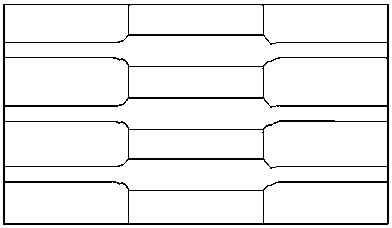
When the auxiliary grid lines are printed on the silicon wafer again, due to the existence of this height difference, the screen plate is deformed due to extrusion at the edge of the main grid lines, resulting in the deformation of the printed auxiliary grid lines, and the height and width are reduced. In severe cases The thin grid is disconnected at the place where it overlaps with the main grid line, thus affecting the collection of current by the auxiliary grid line (such as Figure 4 As shown, the circle is a broken grid)
When there are many broken grids, the photoelectric conversion efficiency of the battery sheet is reduced, resulting in loss
Even undisconnected auxiliary grid lines have reliability risks during the long-term use of components

Method used


Image

  • Screen printing plate used for crystal silicon solar cell step-by-step printing technology
  • Screen printing plate used for crystal silicon solar cell step-by-step printing technology
  • Screen printing plate used for crystal silicon solar cell step-by-step printing technology

Examples


Embodiment Construction

[0015] The present invention will be described in further detail below in conjunction with the accompanying drawings.

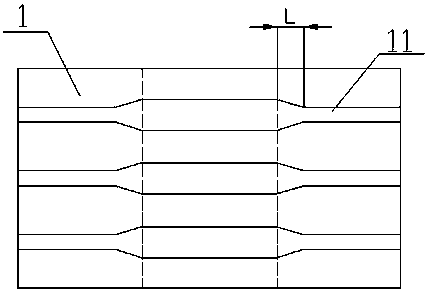
[0016] Such as Figure 1~3 As shown, a screen for step-by-step printing process of crystalline silicon solar cells, including a main grid screen and a sub-grid screen 1, corresponding to a main grid line 2 on the main grid screen, and a main grid line 2 on the sub-grid screen There are auxiliary grid lines 11 corresponding to the plate 1, and the width of the auxiliary grid lines 11 on the auxiliary grid plate 1 is at a distance from the edge of the corresponding position of the main grid line 2 on the main grid plate ( figure 1 The positions of the two dotted lines in the center gradually widen at a certain distance L from the edge of the main grid line, and the width reaches the maximum at the overlap with the position of the main grid line 2.

[0017] The width of the sub-grid line 11 on the sub-grid screen plate 1 is gradually widened at a distance of 1...


PUM


Abstract

The invention relates to a screen printing plate used for a crystal silicon solar cell step-by-step printing technology. The screen printing plate comprises a main grid screen printing plate body andan auxiliary grid screen printing plate body; a main grid line is arranged on the main grid screen printing plate body in a corresponding mode, and an auxiliary grid line is arranged on the auxiliarygrid screen printing plate body in a corresponding mode; and the width of the auxiliary grid line on the auxiliary grid screen printing plate body is gradually widened at a certain distance L away from the edge of the corresponding position of the main grid line on the main grid screen printing plate body and reaches the maximum at position where the auxiliary grid line and the main grid line areoverlapped. According to the screen printing plate used for the crystal silicon solar cell step-by-step printing technology, the problem of grid breaking of the main grid position corresponding to theauxiliary grid screen printing plate body in the solar cell step-by-step printing process, and the collecting efficiency of the current is improved accordingly.

Description

technical field [0001] The invention relates to the field of production and manufacture of crystalline silicon solar cells, and specifically discloses a screen plate for a step-by-step printing process of crystalline silicon solar cells. Background technique [0002] With the continuous maturity and progress of crystalline silicon solar cell technology, cost has gradually become the first issue to be considered in cell process optimization and new technology development; currently, the main grid and auxiliary grid are separated and designed between two screens by using a step-by-step printing process Above all, the manufacturing cost is greatly reduced by using different silver pastes for the main grid and the auxiliary grid and reducing the unit consumption of silver paste. The existing step-by-step printing screen design is simply to split the main grid and the sub-grid into two screens, without considering the impact of the main grid pattern on the battery sheet on the su...

Claims


Application Information

Patent Timeline
IPC IPC(8): B41F15/34H01L31/18
CPCB41F15/34H01L31/1876Y02E10/50Y02P70/50
Inventor 薛娇
Owner 镇江立中机械设备有限公司
Learn More