Glass warehousing device and glass transportation method based on optional cutting
A glass and storage technology, which is applied in the storage device and handling field based on matching and cutting glass, can solve the problems of time consumption and affecting glass cutting efficiency, and achieve the effect of improving efficiency and site use efficiency
Pending Publication Date: 2018-06-22
TAIAN FEICHI AUTOMATION EQUIP
0 Cites 0 Cited by
AI-Extracted Technical Summary
Problems solved by technology
After one type of glass is cut and sliced, when another type of glass needs to be cut, the glass on the glass shelf should be hoisted away, and then another type of glass should be hoisted over, or there is no glass on the glass shelf, and a package of glass should be hung directly On the glass shelf, it should also be noted that the original glass sheet...
Method used
3, owing to having designed middle horizontal support guide rail 85, the first vertical support guide rail 71, the second vertical support guide rail 72, the 3rd vertical support guide rail 73 and the 4th vertical support guide rail 74, form motion track, realized to treat cutting Transshipment of glass plates.
[0051] In the present invention, the storage areas in different regions formed by the first horizontal support guide rail 81, the second horizontal support guide rail 82, the third horizontal support guide rail 83 and the fourth horizontal support guide rail 84 and the first storage area in the same area A horizontal support guide rail 81, a second horizontal support guide rail 82, a third horizontal support guide rail 83 and a fourth horizontal support guide rail 84 are used to distinguish the glass of differe...
Abstract
The invention provides a glass warehousing device and a glass transportation method based on optional cutting. The glass warehousing device comprises a transfer frame (1), a frame device and a rail device, wherein the transfer frame (1) is used for loading to-be-cut glass plates; the frame device is arranged at the periphery of a glass cutting device (2) and is used for storing the transfer frame(1); the rail device is arranged between the frame device and the glass cutting device (2) and is used for the motion of the transfer frame (1); the transfer frame (1) is used for storing different specifications of to-be-cut glass plates; the frame device is used for placing the transfer frame (1); the rail device is used for the transfer frame (1) to move to the periphery of the glass cutting device (2); and an overall bag of raw glass sheets no longer need to be vertically placed on an A-shaped glass frame or an L-shaped glass frame which has a certain inclination angle, so the glass cutting efficiency is improved.
Application Domain
Charge manipulationStorage devices +2
Technology Topic
EngineeringCutting glass +1
Image
Examples
- Experimental program(1)
Example Embodiment
[0031] According to the review guidelines, terms such as "having", "comprising" and "including" used in the present invention should be understood as not deriving the presence or addition of one or more other elements or combinations thereof.
[0032] In the description of the present invention, it should be noted that the terms "center", "upper", "lower", "left", "right", "vertical", "horizontal", "inner", "outer" etc. The indicated orientation or positional relationship is based on the orientation or positional relationship shown in the drawings, and is only for the convenience of describing the present invention and simplifying the description, rather than indicating or implying that the referred device or element must have a specific orientation, or in a specific orientation. construction and operation, therefore, should not be construed as limiting the invention. In addition, the terms "first", "second", and "third" are used for descriptive purposes only, and should not be construed as indicating or implying relative importance.
[0033] In the description of the present invention, it should be noted that unless otherwise specified and limited, the terms "installation", "connection" and "connection" should be understood in a broad sense, for example, it can be a fixed connection or a detachable connection. Connected, or integrally connected; it may be mechanically connected or electrically connected; it may be directly connected or indirectly connected through an intermediary, and it may be the internal communication of two components. Those of ordinary skill in the art can understand the specific meanings of the above terms in the present invention in specific situations.
[0034] In addition, the technical features involved in the different embodiments of the present invention described below may be combined with each other as long as there is no conflict with each other.
[0035] The following will clearly and completely describe the technical solutions in the embodiments of the present invention with reference to the accompanying drawings in the embodiments of the present invention. Obviously, the described embodiments are only some, not all, embodiments of the present invention. Based on the embodiments of the present invention, all other embodiments obtained by persons of ordinary skill in the art without making creative efforts belong to the protection scope of the present invention.
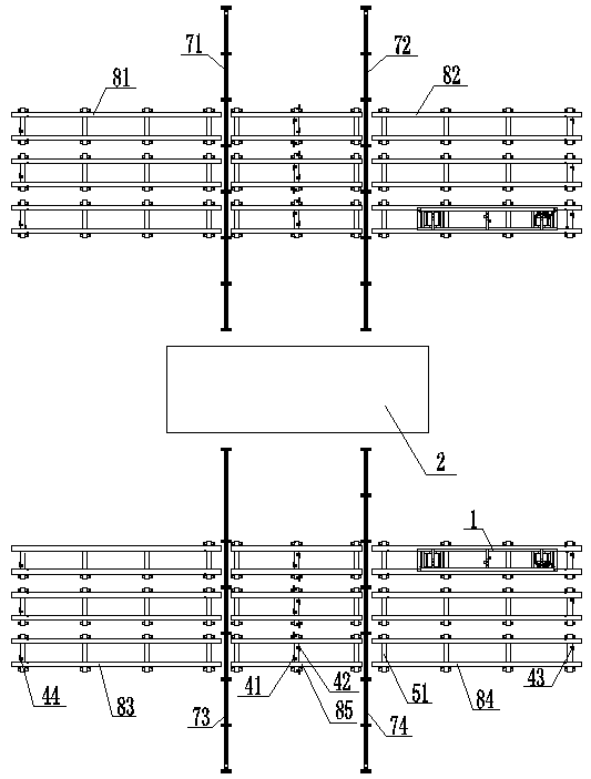
[0036] A storage device based on matching cut glass, figure 1 As the first embodiment of the present invention, this embodiment will be described in detail in conjunction with the accompanying drawings, including a transfer frame 1, a first horizontal support guide rail 81, a second horizontal support guide rail 82, a third horizontal support guide rail 83, and a fourth horizontal support guide rail. Guide rail 84, the middle horizontal support guide rail 85, the first vertical support guide rail 71, the second vertical support guide rail 72, the third vertical support guide rail 73, the fourth vertical support guide rail 74, sleepers 51, the first limit switch 41, the second limit switch Bit switch 42, the 3rd limit switch 43 and the 4th limit switch 44,
[0037] A first vertical support guide rail 71 and a second vertical support guide rail 72 are provided on the rear side of the glass cutting device 2 and a third vertical support guide rail 73 and a fourth vertical support guide rail 74 are provided on the front side of the glass cutting device 2, Between the first vertical support guide rail 71 and the second vertical support guide rail 72 and between the third vertical support guide rail 73 and the fourth vertical support guide rail 74, an intermediate horizontal support guide rail 85 is respectively arranged, on the left side of the first vertical support guide rail 71 The side is provided with a first horizontal support guide rail 81 and a second horizontal support guide rail 82 is provided on the right side of the second vertical support guide rail 72 , and a third horizontal support guide rail 83 is provided on the left side of the third vertical support guide rail 73 And the 4th horizontal support rail 84 is provided with the right side face of the 4th vertical support rail 74, the first horizontal support rail 81, the second horizontal support rail 82, the 3rd horizontal support rail 83, the 4th horizontal support rail 84 and the middle The horizontal support guide rails 85 are respectively arranged to be connected with the foundation surface through the sleepers 51 and the first vertical support guide rail 71, the second vertical support guide rail 72, the third vertical support guide rail 73 and the fourth vertical support guide rail 74 are respectively arranged to be connected with the foundation surface, A first limit switch 41 and a second limit switch 42 are respectively arranged on the sleepers 51 connected to the middle cross support rail 85 and arranged as the sleepers 51 connected to the first cross support guide rail 81 and the third cross support guide rail 83 The fourth limit switch 44 is respectively arranged on the top, and the third limit switch 43 is respectively arranged on the crossties 51 connected to the second horizontal support guide rail 82 and the fourth horizontal support guide rail 84. On the first vertical support guide rail 71, Rollers are respectively arranged on the second vertical support guide rail 72 , the third vertical support guide rail 73 and the fourth vertical support guide rail 74 .
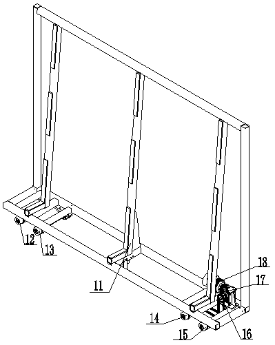
[0038] In this embodiment, the transfer frame 1 is configured to include a support frame 11, a first shaft wheel 12, a second shaft wheel 13, a third shaft wheel 14, a fourth shaft wheel 15, a chain transmission device 16, a speed reducer 17 and The motor 18 is also provided with a first shaft wheel 12 and a second shaft wheel 13 at the front end of the bottom end face of the support frame 11, and a third shaft wheel is respectively arranged at the rear end of the bottom end face of the support frame 11. 14 and the fourth shaft wheel 15 and the reducer 17 and the motor 18 are arranged on the support frame 11, the input end shaft of the reducer 17 is arranged to be coupled with the output end shaft of the motor 18 and the output end shaft of the reducer 17 is connected to the third A chain drive 16 is arranged between the shaft wheel 14 and the fourth shaft wheel 15, and the first shaft wheel 12, the second shaft wheel 13, the third shaft wheel 14 and the fourth shaft wheel 15 are respectively arranged on the first horizontal support guide rail 81 , the second horizontal support guide rail 82, the third horizontal support guide rail 83 and the fourth horizontal support guide rail 84 and the support frame 11 is arranged as an L-shaped frame, the first shaft wheel 12, the second shaft wheel 13, the third shaft wheel 14 and The 4th shaft wheel 15 is arranged as the walking shaft that has roller on the end of fixed shaft, and the driven wheel of chain transmission 16 is arranged to be connected with the 3rd shaft wheel 14 and the 4th shaft wheel 15 respectively and the driving of chain transmission 16 The wheel is arranged to be shaft-coupled with the output end of the speed reducer 17 .
[0039] By the transfer frame 1, the supporting connection points to the first horizontal support guide rail 81, the second horizontal support guide rail 82, the third horizontal support guide rail 83 and the fourth horizontal support guide rail 84 are formed, and the first shaft wheel 12, the second shaft wheel The wheel 13, the third shaft wheel 14 and the fourth shaft wheel 15 realize the connection with the first horizontal support guide rail 81, realize the connection with the second horizontal support guide rail 82, and realize the connection with the third horizontal support guide rail 83 , has realized the connection with the 4th horizontal support guide rail 84, has realized the carrier connection of the glass plate to be cut by the support frame 11, has realized that the transfer frame 1 drives the glass plate to be cut by the chain transmission device 16, the speed reducer 17 and the motor 18. movement of the glass plate.
[0040] In this embodiment, the first horizontal support guide rail 81, the second horizontal support guide rail 82, the third horizontal support guide rail 83, the fourth horizontal support guide rail 84 and the middle horizontal support guide rail 85 are respectively arranged as I-shaped beam-shaped bodies and two The first horizontal support guide rail 81 is set to be arranged in parallel on the sleeper 51, the two second horizontal support guide rails 82 are arranged to be arranged in parallel on the sleeper 51 and the two third horizontal support guide rails 83 are arranged to be arranged in parallel on the sleeper 51 Above, the two fourth horizontal support rails 84 are arranged in parallel on the sleeper 51 and the two middle horizontal support guide rails 85 are arranged in parallel on the sleeper 51 .
[0041] By the first horizontal support guide rail 81, the second horizontal support guide rail 82, the third horizontal support guide rail 83, the fourth horizontal support guide rail 84 and the middle horizontal support guide rail 85, the support connection point to the transfer frame 1 is formed, and the first horizontal support guide rail Support guide rail 81, the second horizontal support guide rail 82, the 3rd horizontal support guide rail 83, the 4th horizontal support guide rail 84, have realized the connection with transfer frame 1, by the middle horizontal support guide rail 85, have realized the second with transfer frame 1 Positioning connection between a vertical support guide rail 71 and the second vertical support guide rail 72 , between the third vertical support guide rail 73 and the fourth vertical support guide rail 74 .
[0042]In this embodiment, the first vertical support guide rail 71, the second vertical support guide rail 72, the third vertical support guide rail 73 and the fourth vertical support guide rail 74 are respectively arranged as I-shaped beam-shaped bodies and the first vertical support guide rail 71 and the second vertical support guide rail 71 Two vertical support guide rails 72 are set to be arranged in parallel, the third vertical support guide rail 73 and the fourth vertical support guide rail 74 are arranged to be distributed in parallel arrangement and the first vertical support guide rail 71, the second vertical support guide rail 72, the third vertical support guide rail The guide rail 73 and the fourth vertical support guide rail 74 are respectively arranged to connect with the ground surface through bolts,
[0043] The upper end face of the first vertical support rail 71, the upper end face of the second vertical support rail 72, the upper end face of the third vertical support rail 73, and the upper end face of the fourth vertical support rail 74 are arranged to be aligned with the middle horizontal support rail. The upper end face of 85 is distributed in drop mode.
[0044] By the first vertical support guide rail 71, the second vertical support guide rail 72, the third vertical support guide rail 73 and the fourth vertical support guide rail 74, the support connection point to the transfer frame 1 is formed, and the first vertical support guide rail 71, the second vertical support guide rail 74 The vertical support guide rail 72 , the third vertical support guide rail 73 and the fourth vertical support guide rail 74 realize the connection with the transfer frame 1 moving to the glass cutting device 2 .
[0045] In this embodiment, the sleepers 51 are arranged as trapezoidal beam-shaped bodies and the sleepers 51 are arranged to be connected to the foundation surface through bolts, and the sleepers 51 are respectively arranged to straddle the ends of the first horizontal support guide rail 81 and the second horizontal support guide rail 82. , the end of the third horizontal support rail 83, the end of the fourth horizontal support rail 84 and the end of the middle horizontal support rail 85.
[0046] By the crossties 51, the supporting connection points to the first cross support rail 81, the second cross support rail 82, the third cross support rail 83, the fourth cross support rail 84 and the middle cross support rail 85 are formed, and the cross sleepers 51 realize Realized the carrier connection with the first horizontal support guide rail 81, realized the carrier connection with the second horizontal support guide rail 82, realized the carrier connection with the third horizontal support guide rail 83, realized the carrier connection with the fourth horizontal support guide rail 84 , realizing the carrier connection with the middle horizontal support guide rail 85 .
[0047] In this embodiment, the first limit switch 41, the second limit switch 42, the third limit switch 43 and the fourth limit switch 44 are respectively set as travel switches and the first limit switch 41 and the second limit switch The switch 42 is set to be dislocated and distributed on the crossties 51 connected to the middle cross support rail 85, and the fourth limit switch 44 is respectively arranged on the outer sides connected to the first cross support guide rail 81 and the third cross support guide rail 83. On the sleeper 51 and the third limit switch 43 is respectively arranged on the sleeper 51 on the outer side connected with the second horizontal support guide rail 82 and the fourth horizontal support guide rail 84, the input port of the first limit switch 41, the second limit switch The input port of the switch 42 , the input port of the third limit switch 43 and the input port of the fourth limit switch 44 are respectively set to be connected to the controller of the transfer rack 1 .
[0048] By the first limit switch 41, the second limit switch 42, the third limit switch 43 and the fourth limit switch 44, the support connection point to the crossties 51 and the transfer frame 1 is formed, by the first limit switch 41 , the second limit switch 42, the third limit switch 43 and the fourth limit switch 44 have realized the connection with the crossties 51, and by the first limit switch 41 and the third limit switch 43, the second limit switch 43 has been realized. The positioning connection of the transfer frame 1 moving on the horizontal support guide rail 82 and the fourth horizontal support guide rail 84 is realized by the second limit switch 42 and the fourth limit switch 44 to the first horizontal support guide rail 81 and the third horizontal support guide rail 81. The positioning connection of the transfer frame 1 moving on the guide rail 83.
[0049] In this embodiment, the transfer frame 1, the first horizontal support guide rail 81, the second horizontal support guide rail 82, the third horizontal support guide rail 83, the fourth horizontal support guide rail 84, the crossties 51 and the glass cutting device 2 are arranged according to the corner The storage mode is distributed and the horizontal support guide rail 85, the first vertical support guide rail 71, the second vertical support guide rail 72, the third vertical support guide rail 73, the fourth vertical support guide rail 74 and the crossties 51 and the glass cutting device 2 are arranged as Distributed according to the way of the middle channel, the transfer frame 1 and the crossties 51 and the first limit switch 41, the second limit switch 42, the third limit switch 43 and the fourth limit switch 44 are arranged to be distributed according to the way of positioning and braking , two first horizontal support rails 81, a transfer frame 1 and a sleeper 51 are arranged to form a set of upper left storage parts and two second horizontal support guide rails 82, a transfer frame 1 and a sleeper 51 are arranged to form a set of lower left storage parts Storage parts, two third horizontal support guide rails 83, a transfer frame 1 and a sleeper 51 are arranged to form a group of upper right storage parts and two fourth horizontal support guide rails 84, a transfer frame 1 and a sleeper 51 are arranged to form a set A set of lower right storage parts, a set of upper left storage parts, a set of lower left storage parts, a set of upper right storage parts and a set of lower right storage parts are respectively arranged at the corners of the glass cutting device 2 .
[0050] A method for handling glass based on matching cut, the present invention will be further described below in conjunction with the examples, and the following examples are intended to illustrate the present invention rather than further limit the present invention. The steps are: put the glass plates to be cut on the transfer rack 1 according to different specifications, and then install the transfer racks 1 with glass plates to be cut of different specifications on the first horizontal support guide rail 81 and the second horizontal support guide rail respectively. 82. On the third horizontal support guide rail 83 and the fourth horizontal support guide rail 84, when it is necessary to process a glass plate to be cut of a specification, start the motor 18 of the transfer frame 1 of the glass plate to be cut in this specification , through the chain transmission device 16 and the speed reducer 17, the third shaft wheel 14 and the fourth shaft wheel 15 are driven to rotate, so that the transfer frame 1 of the glass plate to be cut of this specification is moved to the first vertical support guide rail 71 and the second vertical support rail 71. On the sleepers 51 between the vertical support guide rails 72 or on the sleepers 51 between the third vertical support guide rails 73 and the fourth vertical support guide rails 74, the first limit switch 41 and the second limit switch 42 realize this specification. The transfer frame 1 of the glass plate to be cut is positioned on the first vertical support guide rail 71 and the second vertical support guide rail 72 or on the third vertical support guide rail 73 and the fourth vertical support guide rail 74, and pushes the glass plate to be cut of this specification The transfer rack 1 moves the first vertical support guide rail 71 and the second vertical support guide rail 72 or the third vertical support guide rail 73 and the fourth vertical support guide rail 74, and puts the transfer rack 1 of the glass plate to be cut in this specification side of the glass cutting device 2, so that the glass plate to be cut of this specification is placed on the glass cutting device 2, when the transfer frame 1 moves on the first horizontal support guide rail 81 and the third horizontal support guide rail 83, by the fourth limit The position switch 44 performs positioning braking, and when the transfer frame 1 moves on the second horizontal support guide rail 82 and the fourth horizontal support guide rail 84, the positioning braking is performed by the third limit switch 43 .
[0051] In the present invention, the storage areas in different areas formed by the first horizontal support rail 81 , the second horizontal support rail 82 , the third horizontal support rail 83 and the fourth horizontal support rail 84 and the first horizontal support in the same area The guide rail 81 , the second horizontal support guide rail 82 , the third horizontal support guide rail 83 and the fourth horizontal support guide rail 84 distinguish the glass of different specifications in detail. Through the first horizontal support guide rail 81 and the second horizontal support guide rail 82 , the third horizontal support guide rail 83 and the fourth horizontal support guide rail 84 and the middle horizontal support guide rail 85, the first vertical support guide rail 71, the second vertical support guide rail 72, the third vertical support guide rail 73 and the fourth vertical support guide rail 74 formed Different transport channels combine the storage and transport of glass of different specifications, which improves the cutting efficiency of glass. Through the transfer frame 1, stacked storage of glass is prevented and the integrity rate of glass is guaranteed.
[0052] In the second embodiment of the present invention, the transfer frame 1 for reloading the main body, the frame device for supporting and the track device for regulating the movement route are connected to each other according to the peripheral storage area and the intermediate channel.
[0053] In this embodiment, the transfer frame 1 and the frame device are connected with the track device in such a way that the storage areas of the slices are distributed at intervals.
[0054] In this embodiment, the frame device is arranged as a frame surrounding the glass cutting device 2 .
[0055] In this embodiment, the frame device is configured as a three-dimensional frame.
[0056] In this embodiment, the frame device is configured to include a first horizontal support rail 81, a second horizontal support rail 82, a third horizontal support rail 83 and a fourth horizontal support rail 84 and the first horizontal support rail 81, the second horizontal support rail The supporting guide rail 82 , the third horizontal supporting guide rail 83 and the fourth horizontal supporting guide rail 84 are disposed in a four-corner manner.
[0057] In this embodiment, the track device is configured to include the middle horizontal support rail 85, the first vertical support rail 71, the second vertical support rail 72, the third vertical support rail 73 and the fourth vertical support rail 74 and the middle horizontal support rail 85. The first vertical support guide rail 71 , the second vertical support guide rail 72 , the third vertical support guide rail 73 and the fourth vertical support guide rail 74 are arranged to be distributed according to two interval rails.
[0058] In this embodiment, a first accessory device is also included and the first accessory device is configured to be coupled with the rail device, and the first accessory device is configured as a sleeper 51 .
[0059] In this embodiment, a second accessory device is also included and the second accessory device is configured to be coupled with the first accessory device, and the second accessory device is configured to include a first limit switch 41, a second limit switch 42, a second limit switch The three limit switches 43 and the fourth limit switch 44 as well as the first limit switch 41 , the second limit switch 42 , the third limit switch 43 and the fourth limit switch 44 are configured to output positioning signals.
[0060] The second embodiment of the present invention is based on the first embodiment,
[0061] The present invention has following characteristics:
[0062] 1. Due to the design of the transfer frame 1, the frame device and the track device, the glass plates to be cut of different specifications are stored through the transfer frame 1, the transfer frame 1 is placed through the frame device, and the transfer frame 1 is moved to the In the periphery of the glass cutting device 2, the whole package of glass original sheets is no longer placed vertically on the A-shaped glass frame or the L-shaped glass frame with a certain inclination angle, so the efficiency of glass cutting is improved.
[0063] 2. Due to the design of the first horizontal support guide rail 81, the second horizontal support guide rail 82, the third horizontal support guide rail 83 and the fourth horizontal support guide rail 84, the four corners of the glass cutting device 2 form the glass plate to be cut. Storage interval.
[0064] 3. Due to the design of the middle horizontal support guide rail 85, the first vertical support guide rail 71, the second vertical support guide rail 72, the third vertical support guide rail 73 and the fourth vertical support guide rail 74, the movement track is formed, and the glass plate to be cut is realized. of transshipment.
[0065] 4. Due to the design of the first limit switch 41 , the second limit switch 42 , the third limit switch 43 and the fourth limit switch 44 , the automatic positioning of the transfer rack 1 is realized.
[0066] 5. Due to the design of the sleeper 51, the reinforcement of the first horizontal support rail 81, the second horizontal support rail 82, the third horizontal support rail 83, the fourth horizontal support rail 84 and the middle horizontal support rail 85 has been realized.
[0067] 6. Due to the design of the technical features of the present invention, the tests show that the various performance indicators of the present invention are at least 1.7 times that of the existing various performance indicators. Very good market value with appraisal.
[0068] There are other technical features that are connected with the transfer frame 1, the frame device and the track device of the peripheral storage area and the intermediate channel, which are all one of the embodiments of the present invention, and each technical feature of the above-mentioned embodiments can be combined arbitrarily , in order to meet the requirements of the Patent Law, Patent Implementation Regulations and Examination Guidelines, the embodiments of all possible combinations of the technical features in the above embodiments are not described again.
[0069]Therefore, in the technical field of storage devices and handling methods based on matching cut glass, any frame that includes a transfer rack 1 for loading glass sheets to be cut, a frame that is arranged on the periphery of the glass cutting device 2 and is used to store the transfer rack 1 The technical content of the device, the track device arranged between the frame device and the glass cutting device 2 and used for the movement of the transfer frame 1 is within the protection scope of the present invention.
PUM


Description & Claims & Application Information
We can also present the details of the Description, Claims and Application information to help users get a comprehensive understanding of the technical details of the patent, such as background art, summary of invention, brief description of drawings, description of embodiments, and other original content. On the other hand, users can also determine the specific scope of protection of the technology through the list of claims; as well as understand the changes in the life cycle of the technology with the presentation of the patent timeline. Login to view more.
Similar technology patents
Control circuit and method for a buck-boost power converter
Owner:RICHTEK TECH
Process for producing isoprenoid compounds by microorganisms and a method for screening compounds with antibiotic or weeding activity
Owner:KYOWA HAKKO KOGYO CO LTD
Large multi-sensor integration electric claw
Owner:SHANGHAI JIAO TONG UNIV
System and method to provide lubrication for a plug-in hybrid
Owner:FORD GLOBAL TECH LLC
Classification and recommendation of technical efficacy words
- Improve site use efficiency
- Improve efficiency
An intelligent tire frame and a method for supporting a ship hull by the intelligent tire frame
Owner:DALIAN MARITIME UNIVERSITY
Video coding methods and apparatuses
Owner:MICROSOFT TECH LICENSING LLC
Dynamic player groups for interest management in multi-character virtual environments
Owner:MICROSOFT TECH LICENSING LLC
Method and apparatus for controlling a selectable voltage audio power output stage
Owner:CIRRUS LOGIC INC
Wireless power transmitter and power transmission method thereof
Owner:LG INNOTEK CO LTD