
Fluorescent liquid laser light-emitting device and manufacturing method thereof

A light-emitting device and fluorescent liquid technology, which is applied to lighting devices, optical elements used to change the spectral characteristics of emitted light, components of lighting devices, etc., can solve problems such as difficult installation, maintenance, bulky lamps, and high heat production , to achieve the effects of rapid heat conduction and heat dissipation, good light efficiency and high production efficiency

Pending Publication Date: 2018-06-22
RENMIN UNIVERSITY OF CHINA
View PDF7 Cites 1 Cited by
  • Summary
  • Abstract
  • Description
  • Claims
  • Application Information

AI Technical Summary

Problems solved by technology

However, a disadvantage of ordinary LED lamps is that although they have greatly improved in terms of energy saving or lifespan, their heat output is also high. It can be said that ordinary LED lamps use energy in addition to the useful power of light. Energy is generated in the form of heat. As a result, ordinary LED lamps must use radiators. The greater the power, the greater the heat generated, and the larger the radiator
The result of this defect is that the lamps are bulky, overweight, and difficult to install, use and maintain.

Method used


Image

  • Fluorescent liquid laser light-emitting device and manufacturing method thereof
  • Fluorescent liquid laser light-emitting device and manufacturing method thereof
  • Fluorescent liquid laser light-emitting device and manufacturing method thereof

Examples


Embodiment Construction

[0026] The present invention will be described in detail below in conjunction with the accompanying drawings and embodiments. However, it should be understood that the accompanying drawings are provided only for better understanding of the present invention, and they should not be construed as limiting the present invention.

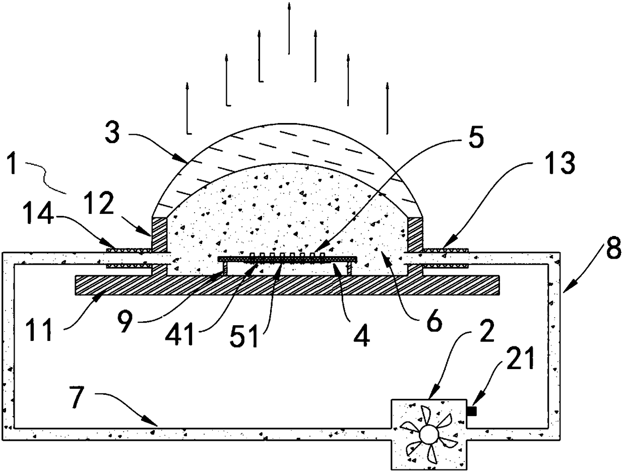
[0027] Such as Figure 1 ~ Figure 4 As shown, a fluorescent liquid laser light-emitting device provided by the present invention includes a main cavity 1, a stirring pump 2, a lens 3, a circuit board 4, an LD excitation light source 5, and a liquid fluorescent material 6 filled inside the light-emitting device.

[0028] The main cavity 1 includes a base 11. The top of the base 11 is fixed with a cylindrical cavity 12 with an upward opening. The top of the cavity 12 is sealed and bonded with the lens 3. The opposite ends of the side of the cavity 12 are provided with a liquid inlet 13 and a liquid outlet. 14. The liquid inlet 13 and the liquid outlet 14 ...


PUM


Abstract

The invention relates to a fluorescent liquid laser light-emitting device and a manufacturing method thereof. The fluorescent liquid laser light-emitting device is characterized by comprising a main cavity, a stirring pump, a lens, a circuit board, LD excitation light-emitting light sources and a liquid fluorescent material; the main cavity comprises a base; a cylindrical cavity body with an upward opening is fixedly arranged at the top of the base; the top of the cavity body hermetically adheres to the lens; a liquid inlet and a liquid outlet are formed in the two opposite ends of the side surface of the cavity body and are connected to the two ends of a fluorescent liquid guide pipe respectively; the stirring pump is connected to the fluorescent liquid guide pipe; a fluorescent liquid injection port is formed in the stirring pump; the circuit board is fixedly arranged at the top of a base plate inside the cylindrical cavity body through circuit board supporting columns; the top of the circuit board is fixedly welded to the LD excitation light-emitting light sources and communicates with the LD excitation light-emitting light sources; and the liquid fluorescent material fills theinteriors of the cylindrical cavity body and the fluorescent liquid guide pipe. The fluorescent liquid laser light-emitting device and the manufacturing method thereof can be widely applied to the field of light emitting devices.

Description

technical field [0001] The invention relates to the technical field of fluorescent liquid laser light emitting devices, in particular to a fluorescent liquid laser light emitting device and a manufacturing method thereof. Background technique [0002] Since environmental issues have been paid more and more attention in the world, more and more attention has been paid to environmental protection in the field of lighting, and the requirements for how to reduce exhaust emissions and pollution in the field of lighting have gradually become stricter. For this reason, in the field of lighting, how to promote the reduction of exhaust emissions or more energy-saving technical solutions continue to emerge. Although there are certain technical improvements, that is, replacing high-pressure sodium lamps with ordinary LED lamps, although this also has a certain energy-saving effect, the main consideration for this replacement is that the life of ordinary LED lamps is longer than that of...

Claims


Application Information

Patent Timeline
Patent Type & Authority Applications(China)
IPC IPC(8): F21K9/20F21K9/64F21K9/69F21K9/90F21V5/04F21V9/32F21V19/00F21V23/00F21V29/58F21Y115/30
CPCF21K9/20F21K9/64F21K9/69F21K9/90F21V5/04F21V19/0025F21V23/00F21V29/59F21Y2115/30
Inventor 曹永革申小飞
Owner RENMIN UNIVERSITY OF CHINA
Learn More