Aeration drying device and method

A kind of ventilation drying and drying technology, applied in the direction of drying gas arrangement, progressive dryer, drying solid materials, etc., can solve problems such as low drying efficiency of materials, reduce drying cost, improve drying efficiency, and ensure the effect of drying amount of materials

Pending Publication Date: 2018-06-22
SHANDONG QIQUAN ENERGY TECH CO LTD
View PDF20 Cites 2 Cited by
  • Summary
  • Abstract
  • Description
  • Claims
  • Application Information

AI Technical Summary

Problems solved by technology

[0006] The invention provides a ventilation drying device and a ventilation drying method to solve the problem of low drying efficiency of materials in the prior art

Method used


Image

  • Aeration drying device and method
  • Aeration drying device and method
  • Aeration drying device and method

Examples


Embodiment 1

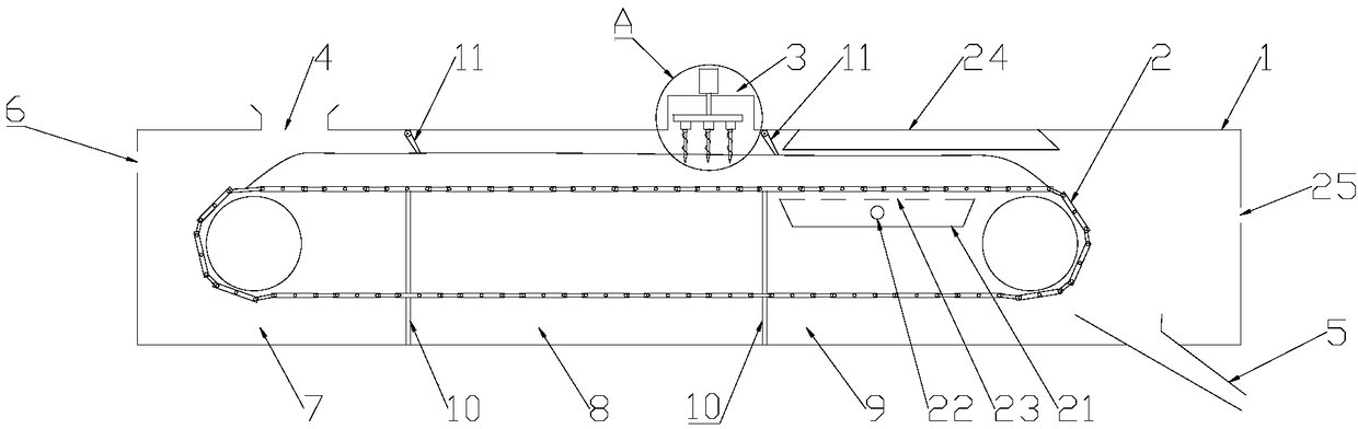
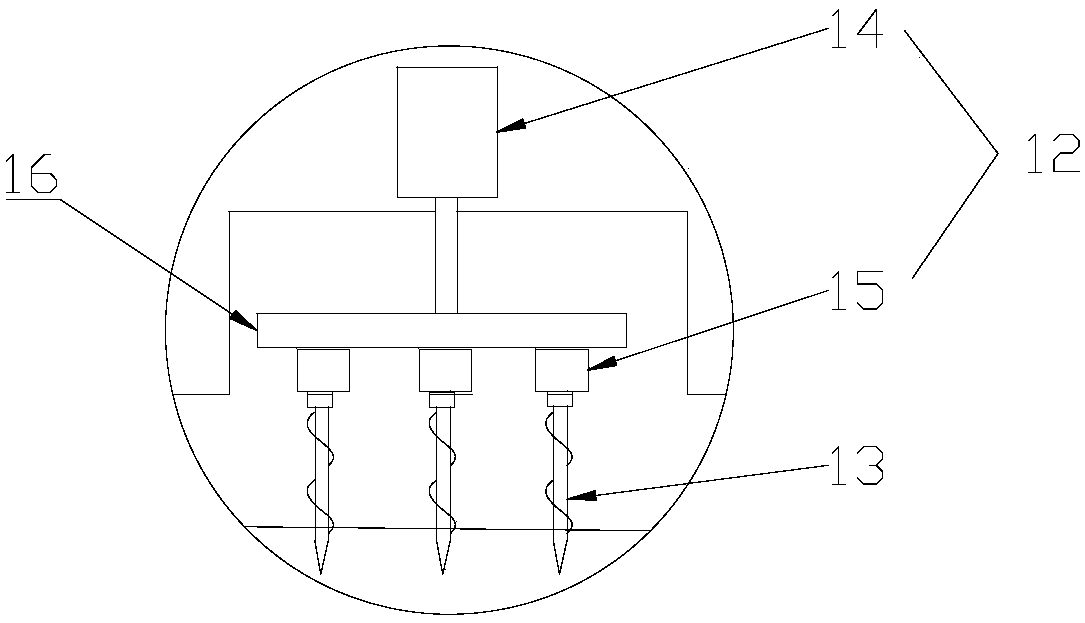
[0031] Embodiment 1 of the present invention provides a ventilating and drying device. The ventilation and drying device includes a shell 1, a conveying plate chain 2 and a punching part 3. The shell 1 is provided with a feed port 4, a discharge port 5, and a first blowing port 6. The inside of the shell 1 is sequentially separated for preheating. Section 7, heat preservation section 8 and drying section 9; the conveyor plate chain 2 is set in the housing 1 and the material is transported from the feed port 4 to the discharge port 5 through the preheating section 7, heat preservation section 8 and drying section 9; The hole part 3 is arranged at the end of the heat preservation section 8 and punches the material.

[0032] The ventilating and drying device provided by Embodiment 1 of the present invention can input materials from the feeding port 4 by setting the feeding port 4 and the discharging port 5 on the casing 1 and setting the conveying plate chain 2 in the casing 1, a...

Embodiment 2

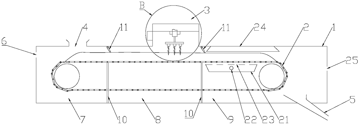
[0064] like Image 6 As shown, Embodiment 2 of the present invention provides a ventilation drying method, and the ventilation drying method uses the ventilation drying device in Embodiment 1. The ventilated drying method includes the following steps: S01, put the material into the shell 1, the shell 1 has a drying channel for drying the material, the drying channel includes a preheating section 7, a heat preservation section 8 and a drying section 9, and the material is in the drying channel S02, the material is preheated in the preheating section 7 to reach the growth temperature of the microorganisms in the material; S03, the microorganisms generate heat in the heat preservation section 8, and the material is punched and / or dried before the material enters the drying section 9 Or turn the material; S04, dry the material in the drying section 9 and discharge the material out of the drying channel.

[0065] Specifically, the operator can put materials into the interior of th...


PUM


Abstract

The embodiment of the invention provides an aeration drying device and method. The aeration drying device comprises a shell, a conveying plate chain and a drilling component. The shell is provided with a feed port, a discharge port and a first blowing port. The interior of the shell is sequentially divided into a preheating section, a heat holding section and a drying section. The conveying platechain is arranged in the shell and conveys materials from the feed port to the discharge port through the preheating section, the heat holding section and the drying section. The drilling component isarranged at the tail end of the heat holding section and conducts drilling on the materials. According to the aeration drying device, the shell is divided into the preheating section, the heat holding section and the drying section; the materials are completely preheated at the preheating section to provide the proper growth temperature for microorganisms in the materials; the microorganisms react to generate heat to evaporate water in the materials at the heat holding section; the drilling component conducts drilling on the materials at the tail end of the heat holding section to guarantee inflowing of dry gas and outflowing of moist gas after the materials go into the drying section; it can be guaranteed that water in the materials is sped up to transfer the mass outwards; the drying process is accelerated, and the drying efficiency is improved.

Description

technical field [0001] The invention relates to the technical field of material drying, in particular to a ventilation drying device and a ventilation drying method. Background technique [0002] Biomass power generation is a kind of renewable energy power generation that uses the biomass energy of biomass to generate power. At present, the commonly used form of biomass power generation is the direct combustion of agricultural and forestry wastes. Direct combustion power generation is to directly burn biomass in a boiler to produce steam to drive a steam turbine and generator to generate electricity. [0003] However, due to the high moisture content of biomass itself, its moisture content has a more prominent impact on its calorific value. Generally, the moisture content of biomass entering the furnace is about 45%. When it is directly burned, it will reduce the combustion temperature, increase the loss of exhaust gas, and reduce the boiler energy consumption. thermal eff...

Claims


Application Information

Patent Timeline
Patent Type & Authority Applications(China)
IPC IPC(8): F26B15/04F26B21/00F26B25/02
CPCF26B15/04F26B21/00F26B25/02
Inventor 冯留建董统玺
Owner SHANDONG QIQUAN ENERGY TECH CO LTD
Why Eureka
Try Eureka