Sucker rod paint spraying airing system
A technology for sucker rods and spray booths, which is applied in the direction of pretreatment surface, device for coating liquid on the surface, coating, etc., which can solve the problems that harmful substances cannot be discharged in time, and the drying time of sucker rods is long, etc. Fast drying, short time effect
- Summary
- Abstract
- Description
- Claims
- Application Information
AI Technical Summary
Problems solved by technology
Method used
Image

Examples
Embodiment Construction
[0020] In order to make the technical problems, technical solutions and beneficial effects to be solved by the present invention clearer, the present invention will be further described in detail below in conjunction with the accompanying drawings and embodiments. It should be understood that the specific embodiments described here are only used to explain the present invention, not to limit the present invention.
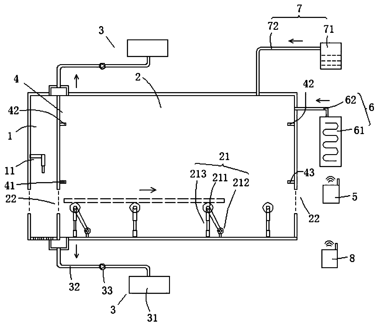
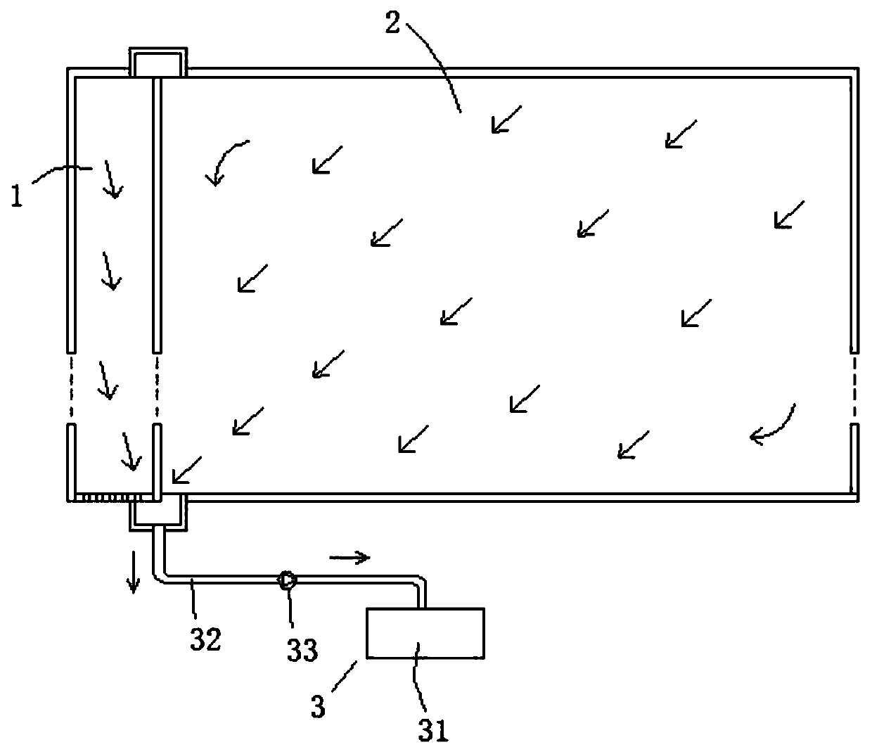
[0021] Please also refer to figure 1 and image 3 , the sucker rod paint drying system provided by the present invention will now be described. The sucker rod paint spraying and drying system includes a paint spraying room 1, a drying room 2, a negative pressure device 3, a detection component 4 and a control terminal 5, a painting device 11 is arranged in the painting room 1, and the drying room 2 is located in the paint spraying room. One side of the room 1 is connected with the painting room 1, and the drying room 2 is provided with a conveying mechanism 21 fo...
PUM
 Abstract
Description
Claims
Application Information