Dissolved gas separation automatic degassing device and method in transformer oil sample

A technology for dissolving gas and transformer oil, applied in measuring devices, material separation, instruments, etc., can solve problems such as deviation of analysis results and low reliability of analysis data

Active Publication Date: 2021-07-06
囯网河北省电力有限公司电力科学研究院 +2
View PDF10 Cites 0 Cited by
  • Summary
  • Abstract
  • Description
  • Claims
  • Application Information

AI Technical Summary

Problems solved by technology

[0004] The purpose of the present invention is to provide an automatic degassing device for the separation of dissolved gas in transformer oil samples, so as to solve the technical problems of large deviations in analysis results and low reliability of analysis data in the prior art

Method used


Image

  • Dissolved gas separation automatic degassing device and method in transformer oil sample
  • Dissolved gas separation automatic degassing device and method in transformer oil sample
  • Dissolved gas separation automatic degassing device and method in transformer oil sample

Examples


Embodiment approach

[0058] Further, see Figure 7 to Figure 10 , as a specific embodiment of the automatic degassing device for separating dissolved gas in transformer oil samples provided by the present invention, the oscillation tray 31 includes two layers of clamping tray bodies 311 and is arranged between the two layers of clamping tray bodies 311 The clamping tray body 312 that is slidably connected with the two layers of the clamping tray body, the clamping tray body 312 is connected with the locking mechanism 32, and the rotary stepping motor 34 is connected with the clamping tray body 311 connected, the clamping tray body 312 corresponds to the holes 37 provided on the two layers of the clamping tray body 311 one by one, and the clamping tray body slides left and right under the action of the locking mechanism, so that all The holes on the clamping tray body and the holes on the clamping tray body are misaligned to clamp the sealed container. In this embodiment, the clamping of the airti...

specific Embodiment

[0075] A specific embodiment of the automatic degassing method provided by the invention is as follows:

[0076] 1. The equipment is powered on and stable.

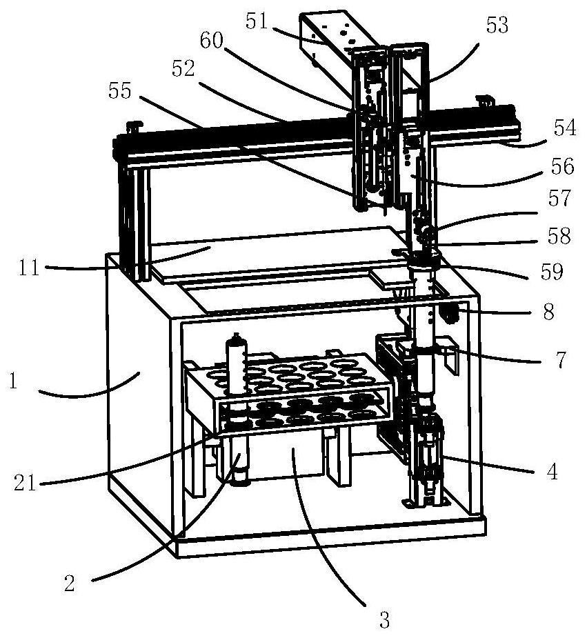
[0077] Use a unified customized 100mL sealed glass syringe to hold the insulating oil sample. For the sake of uniformity, the sealed glass syringe containing the oil sample is called the sealed container 2, and the insulating oil sample is placed in the mechanical vibration tray 31, and the sample loaded into the sealed container 2 is required The volume is greater than or equal to the set value of 40mL, and it is ensured that no air bubbles are introduced into the airtight container 2 . The sample tray can hold up to 15 samples at a time. A 60mL sealed glass syringe can also be used as the sealed container 2.

[0078] 2. Automatically adjust the volume of test oil

[0079] After the equipment installation and setting program is started, firstly, the three-dimensional manipulator grabs the sealed container 2 in order a...


PUM


Abstract

The invention provides an automatic degassing device and method for separating dissolved gas in a transformer oil sample, belonging to the technical field of transformer oil sample analysis, including a constant temperature box, a sealed container, a mechanical oscillation degassing module, an automatic metering and gas taking module, and a three-dimensional manipulator modules and control modules. The automatic degassing device for separating the dissolved gas in the transformer oil sample of the present invention uses a three-dimensional manipulator module to grasp and put back the sealed container, and discharges the redundant oil sample in the sealed container and extracts the oil in the sealed container. The sample gas, in cooperation with the automatic metering and gas extraction module, realizes the precise quantification of the oil sample in the sealed container, replenishes the predetermined volume of carrier gas and extracts the released gas, and uses the mechanical vibration degassing module to realize the vibration degassing of the oil sample , From quantitative measurement of oil samples, gas supply, constant temperature oscillation degassing, outgas transfer to gas quantitative measurement, the control module is used to realize automatic control.

Description

technical field [0001] The invention belongs to the technical field of transformer oil sample analysis, and more specifically relates to an automatic degassing device for separating dissolved gas in a transformer oil sample and an automatic degassing method using the device. Background technique [0002] Using gas chromatography to analyze the content of dissolved gas components in transformer oil is one of the effective methods to judge whether there may be partial discharge or local overheating faults inside the transformer (including other oil-filled electrical equipment). Among the methods for diagnosing internal faults in transformers, chromatographic analysis is more practical than other electrical tests. It can more accurately and sensitively detect early transformer faults. The chromatograph can accurately analyze the types of gases dissolved in transformer oil, Content, etc., in order to judge the faults, defects and damage severity inside the transformer. The insu...

Claims


Application Information

Patent Timeline
Patent Type & Authority Patents(China)
IPC IPC(8): G01N30/06G01N30/18G01N30/24
CPCG01N30/06G01N30/18G01N30/24
Inventor 刘克成张立军马慧芳王娟怡李铭垣
Owner 囯网河北省电力有限公司电力科学研究院
Why Eureka
Try Eureka