Dielectric loss test method and device for collecting contrast current signal by using resistor divider

A resistive voltage divider, current signal technology, applied in voltage dividers, measuring devices, measuring resistance/reactance/impedance, etc., can solve the problem of inability to accurately measure dielectric loss

Pending Publication Date: 2018-06-22
YUNNAN POWER GRID CO LTD ELECTRIC POWER RES INST +1
View PDF11 Cites 2 Cited by
  • Summary
  • Abstract
  • Description
  • Claims
  • Application Information

AI Technical Summary

Problems solved by technology

[0005] The invention provides a dielectric loss testing method and device using a resistance divider to collect a comparison current signal, so as to solve the problem that the current testing method cannot accurately measure the dielectric loss

Method used


Image

  • Dielectric loss test method and device for collecting contrast current signal by using resistor divider
  • Dielectric loss test method and device for collecting contrast current signal by using resistor divider
  • Dielectric loss test method and device for collecting contrast current signal by using resistor divider

Examples


Embodiment Construction

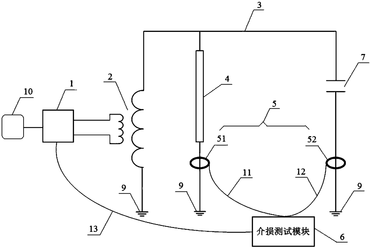
[0042] figure 1 It is a schematic structural diagram of a dielectric loss testing device using a resistive voltage divider to collect a contrast current signal according to Embodiment 1 of the present invention.

[0043] See figure 1 , The dielectric loss test device using a resistance voltage divider to collect a comparison current signal provided by the first embodiment of the present invention includes: a step-up transformer 2, an insulated wire 3, a resistance voltage divider 4, a current measurement coil group 5, and a dielectric loss test module 6. Position 7 to be tested and several grounding terminals 9, of which,

[0044] In the actual dielectric loss test, place a sample, such as a capacitor, in the test position 7. The capacitor is connected with other components to achieve the test of the dielectric loss parameter of the capacitor.

[0045] One end of the secondary winding of the step-up transformer 2 is connected in series with the resistance divider 4 through an insulat...


PUM


Abstract

The invention discloses a dielectric loss test method and device for collecting a contrast current signal by using a resistor divider. The dielectric loss test device comprises a step-up transformer,an insulation wire, the resistor divider, a current measuring coil group, a dielectric loss test module, a position to be tested, and a number of ground terminals. The current measuring coil group isused to collect the values of current flowing through the resistor divider and the position to be tested. The voltage value of the high voltage end of the step-up transformer is determined according to the current value and the resistance value of the resistor divider. The dielectric loss test module calculates the phase difference between the current value of the resistor divider and the currentvalue of the position to be tested to determine the dielectric loss angle of the position to be tested. According to the voltage value of the high voltage end of the step-up transformer and the current value of the position to be tested, the capacitance of the position to be tested is determined. According to the invention, the device is based on the current of the resistor divider, and can trulyand reliably test the relevant parameters of the position to be tested.

Description

Technical field [0001] The invention relates to the technical field of electrical measurement, and in particular to a dielectric loss testing method and device for collecting contrast current signals by using a resistance voltage divider. Background technique [0002] Under the action of an electric field, due to the hysteresis effect of dielectric conductivity and dielectric polarization, the energy loss caused by the insulating material is also called dielectric loss, or dielectric loss for short. Dielectric loss and capacitance test is a highly sensitive test item, which can find out whether there are overall damp, insulation oil deterioration and local defects inside the equipment. [0003] At present, the method used for dielectric loss and capacitance testing is a dielectric loss tester with Xilin bridge as the prototype. When performing dielectric loss testing, the actual test value of dielectric loss is the current flowing through the tested product and The tangent value o...

Claims


Application Information

Patent Timeline
Patent Type & Authority Applications(China)
IPC IPC(8): G01R27/26G01R15/04
CPCG01R15/04G01R27/2694
Inventor 朱启龙刘红文钱国超李昊潘浩孙傲阳
Owner YUNNAN POWER GRID CO LTD ELECTRIC POWER RES INST
Why Eureka
Try Eureka