Geometric parameter correction method for static CT system

A technology of geometric parameters and correction methods, which is used in medical science, instruments for radiological diagnosis, diagnosis, etc. problem, to achieve the effect of simple parameter correction process

Inactive Publication Date: 2018-06-26
SHENZHEN INST OF ADVANCED TECH
View PDF11 Cites 19 Cited by
  • Summary
  • Abstract
  • Description
  • Claims
  • Application Information

AI Technical Summary

Problems solved by technology

[0004] But above-mentioned technique has following shortcoming: 1, can not be applicable to ex vivo CT system (sample rotates, ray source and detector do not move) and in vivo CT system (sample does not move, ray source and detector rotate) simultaneously; 2, cannot Simultaneously correct all 10 geometric parameters of the CT system; 3. The parameter calibration process is complicated (for example, multiple projections of the calibration phantom are required), and it is difficult to repeat it many times

Method used


Image

  • Geometric parameter correction method for static CT system
  • Geometric parameter correction method for static CT system
  • Geometric parameter correction method for static CT system

Examples


Embodiment Construction

[0057]In the following description, numerous specific details are set forth in order to provide a thorough understanding of the invention. The present invention may be practiced without some or all of these specific details. In other instances, well known process operations have not been described in detail in order not to unnecessarily obscure the present invention. While the invention will be described in conjunction with specific embodiments, it will be understood that they are not intended to limit the invention to those embodiments.

[0058] Combine below Figure 1-6 The method for correcting the geometric parameters of the static CT system of the present invention will be described.

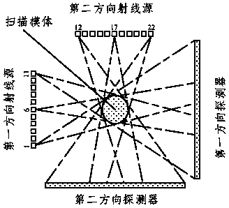
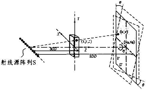
[0059] The present invention provides a method for correcting geometric parameters of a static CT system. The static CT system is composed of multiple ray sources and more than one detector, and the geometric parameters are the geometric parameters between each ray source and the correspo...


PUM


Abstract

The invention provides a geometric parameter correction method for a static CT system. The static CT system is composed of a plurality of ray sources and one or more detectors, and geometric parameters are the geometric parameters of each ray source and the corresponding detector. The method includes the following steps that a, a correction body mold is placed in the static CT system which requires correction of the geometric parameters, and the correction body mold has a small marking ball; b, each ray source triggers rays once to obtain a plurality of projections; c, calculation is conductedto obtain the corrected geometric parameters of the entire static CT system according to the coordinate of the projection center point of the small marking ball in each projection and combination with the known coordinate of the small marking ball in a system to be corrected. The method can be applied to both an in vitro CT system and a living CT system, and all 10 geometric parameters of the CTsystem can be simultaneously corrected. In addition, only each ray source needs to carry out projection on the correction body mold once, and then all the geometric parameters required for CT reconstruction can be obtained.

Description

technical field [0001] The invention relates to a computerized tomography (CT) system in the fields of medicine and industry, in particular to a method for correcting geometric parameters of a static CT system. Background technique [0002] Computed tomography (CT) is an important imaging method to obtain the internal structure information of objects in a non-destructive way. It has many advantages such as high resolution, high sensitivity and multi-level, and is widely used in various medical clinical examination fields. Compared with the traditional CT system, the static CT system has multiple ray sources, and does not require rotation of components such as the X-ray source and the X-ray detector during the data acquisition process, which can reduce costs and shorten the scanning time of CT imaging, and because Static CT has no mechanical movement during the imaging process, which avoids the generation of motion artifacts. [0003] Geometric parameter correction is an imp...

Claims


Application Information

Patent Timeline
Patent Type & Authority Applications(China)
IPC IPC(8): A61B6/03G01N23/04
CPCA61B6/032A61B6/583A61B2560/0223G01N23/04
Inventor 蒋昌辉胡战利梁栋张其阳石伟洪序达高娟郑海荣
Owner SHENZHEN INST OF ADVANCED TECH
Why Eureka
Try Eureka