
Flow mark-free processing mold and method for panel with polished surface

A technology for processing molds without flow marks, which can be used in household appliances, other household appliances, flat products, etc., and can solve the problems of the impact of the surface aesthetics of the formed panel and easy to be stolen.

Pending Publication Date: 2018-06-26
王朝翔
View PDF0 Cites 3 Cited by
  • Summary
  • Abstract
  • Description
  • Claims
  • Application Information

AI Technical Summary

Problems solved by technology

The frosted surface treatment panel can also be called a matte surface treatment panel. The surface has densely packed uneven bumps.
[0004] During the processing of the polished surface treatment panel, the liquid material for the polished surface treatment panel is injected into the cavity of the mold through the material inlet of the mold. Since the polished surface treatment panel needs to pass through the processing screw hole or socket during the injection molding process, The inlet is the starting end of the flow direction of the liquid material, and the end where the liquid material stops flowing after entering the mold cavity from the starting end is the terminal. When the liquid material flows to the terminal (usually the terminal has a socket or screw hole), the temperature difference relationship, resulting in the formation of large or small flow marks, which cannot be eliminated, which will affect the aesthetics of the surface of the formed panel

Method used


Image

  • Flow mark-free processing mold and method for panel with polished surface

Examples


Embodiment Construction

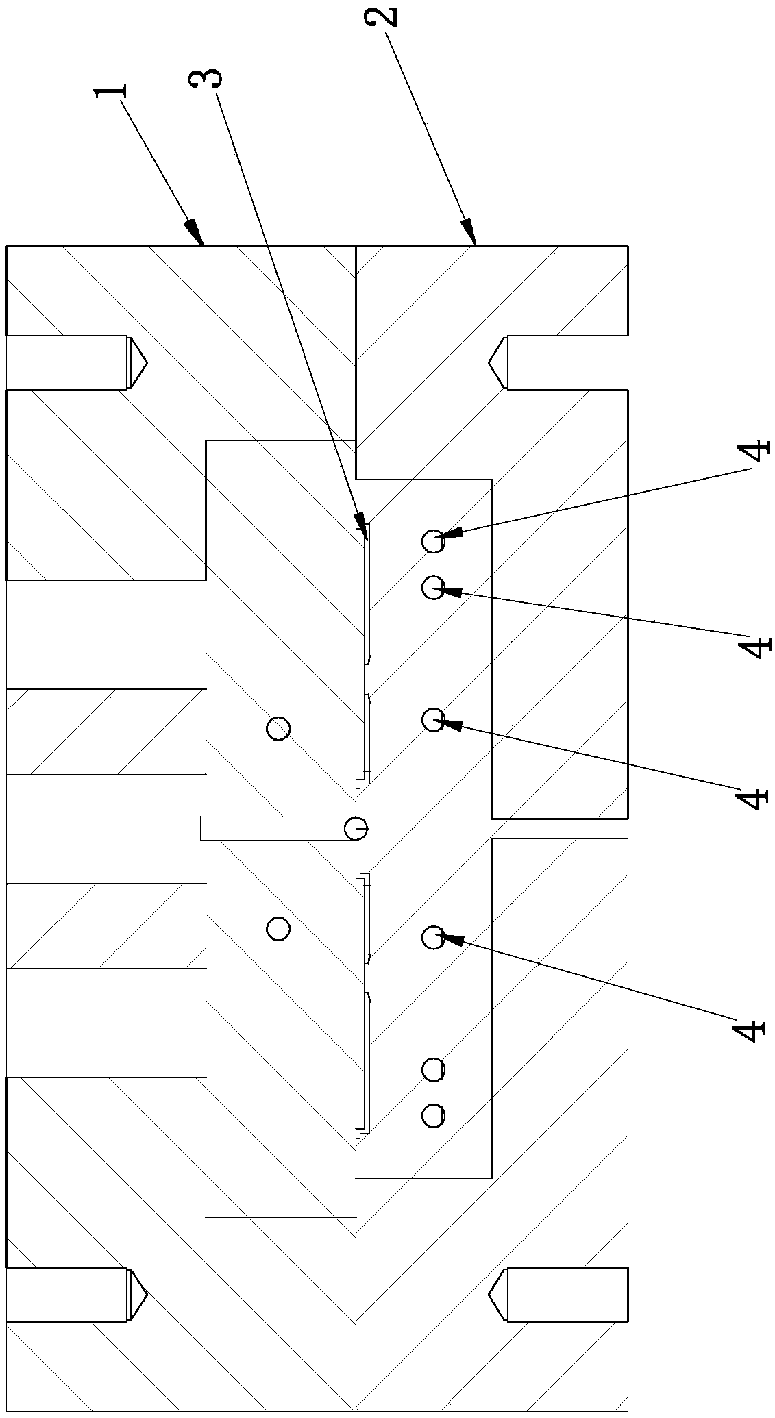
[0013] Such as figure 1 A non-flow mark processing mold for a polished surface treatment panel is shown, including an upper mold 1 and a lower mold 2 that can be fastened with the upper mold 1, and the upper mold 1 and the lower mold 2 are respectively provided with panels for forming The cavity is 3, and the upper mold 1 or the lower mold 2 is provided with a material inlet connected to the cavity, and the upper mold 1 has one end as the inlet end, and the other end is the output end and is isolated from the cavity 3 for heating medium The input heating channel 4 is located at the end of the panel where the liquid material enters the cavity 3 from the feed port and forms a jack or a screw hole. In the above solution, by setting the heating channel 4 on the mold that is isolated from the cavity 3 and at the end of the flow of the liquid material, after the liquid material is injected into the cavity 3 for molding, the heating medium is injected into the heating channel 4 to ma...


PUM


Abstract

The invention relates to a panel with a polished surface, in particular to a flow mark-free processing mold and method for a panel with a polished surface. According to the technical scheme, the flowmark-free processing mold for the panel with the polished surface comprises an upper mold body and a lower mold body which can be combined with the upper mold body. A cavity for forming the panel is formed between the upper mold body and the lower mold body. A feeding port communicating with the cavity is formed in the upper mold body or the lower mold body. A heating channel which is provided with one end serving as an inlet end and the other end serving as an outlet end, isolated from the cavity and used for inputting heating media is formed in the upper mold body. The heating channel is located at the tail end of an insertion hole or a spiral hole formed in the panel after liquid materials enter the cavity via the feeding port. By adoption of the flow mark-free processing mold and method for the panel with the polished surface, surface flow marks are eliminated, the structure is simple, operation is convenient, and the surface aesthetic degree is guaranteed.

Description

technical field [0001] The invention relates to a polished surface treatment panel, in particular to a flow mark-free processing mold for a polished surface treatment panel and a flow mark-free processing method for a polished surface treatment panel. Background technique [0002] There are many types of panels, such as switch panels, TV panels or remote control panels. This type of panel has screw holes or sockets for installation, and the screw holes or sockets and the panel are formed at one time through a special mold. [0003] The panel is divided into a smooth surface treatment panel and a frosted surface treatment panel. The polished surface treatment panel has a smooth surface, high brightness and is not easy to leave debris. The frosted surface treatment panel can also be called a matt surface treatment panel. The surface has densely packed uneven bumps. Its surface is not easy to be scratched, but it is easy to get dirty. [0004] During the processing of the pol...

Claims


Application Information

Patent Timeline
Patent Type & Authority Applications(China)
IPC IPC(8): B29C45/26B29C45/73B29C45/78B29L7/00
CPCB29C45/26B29C45/0025B29C45/73B29C45/78B29L2007/002
Inventor 王朝翔
Owner 王朝翔
Learn More